Frequency counter input stage

Thread Starter

drkblog

Joined Oct 4, 2012
109
Hello again,

As usual, I'm in trouble with a transistor circuit :) But I think I've learned a couple of things already (compared with my previous posts). Yet, as soon as I start modifying the circuit I hesitate. And I'm not sure if my assumptions are correct. Let's see:

I have to measure an analog-signal frequency using both, an Arduino and a Raspberry Pi. For the Arduino case I've used a circuit like this:


Which, after being discussed in this thread I modified a little and worked fine. In the Raspberry Pi case, I want to improve the circuit. I'd like it to switch the transistor on with less than 700mV in the base. So I biased the base with a DC level using a circuit like the old class A amplifier. At first I connected the emitter to 0V but then I had noise being amplified. So I added a preset in order to modify Ve and thus modify the voltage needed at the base for turning on the transistor. I don't know if this is a good idea.

I stated (from the previous circuit) that Ic ≈ 150µA

β ≈ 100 and Vb = 700mV

Ib = 1.5µA

R1 = Vdd - 700mV / (Ib x 10) = 173kΩ
R2 = 700mV / (Ib x 10) = 47 kΩ


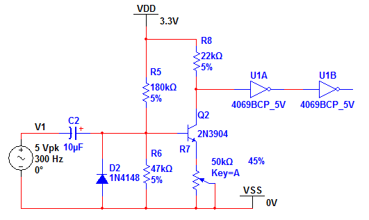
Now the problem here is the input signal es 5V peak to peak but my input circuit has 3.3V source (from RaspberryPi). So when the base is taken over 2.3V the transistor is turned off, as you can see here. I added two orange arrows in the graphic:


There are two questions then:
  1. Is the preset between emitter and ground a proper way for handling the base-voltage threshold?
  2. How do I limit the input for avoiding the 5V problem?
 
Last edited:

shteii01

Joined Feb 19, 2010
4,644
Well. The the 5 volt input can be solved by using voltage divider. Maybe use 1.7 kOhm and 3.3 kOhm resistors to form the voltage divider, then take the voltage across 3.3 kOhm resistor to the board.
 

ScottWang

Joined Aug 23, 2012
7,399
Your problem is not the transistor turned off, that's the transistor over amplifying and get into the saturation area, so it will be like the logical function and shows up a square wave.

Using the divider is one way, the other ways that you can use are reducing the Magnification of the amplifier, or using the pot put on the input pin to limiting the singal as the volume of radio or audio amplifier.

The 1,3 pins of pot to connecting to the input signal, and connecting the input capacitor to the pin 2 of the pot.
 

Thread Starter

drkblog

Joined Oct 4, 2012
109
I will use a preset as I did in the previous circuit for limiting the input as you suggested. It was pretty obvious but I couldn't see it.

But I see the transistor goes into cut area (not saturation area) in the zones I marked.

The red signal is the output of the second not-gate. In the first marked input pulse, you can see the transistor turns on when the input level goes over 1.2V and then it goes off again when it's above 2.3V. The orange arrow marks the extra pulse I get at the output.
 
Last edited:

bertus

Joined Apr 5, 2008
22,276
Hello,

You can even use an 4049 gate as an amplifier.
Here I have even used it for an antenna amplifier for a communication receiver:


Most likely one stage with the meg-ohms resistor will be enough for you.

Bertus
 

Attachments

Last edited:

ScottWang

Joined Aug 23, 2012
7,399
Have you measure the wave form of c of bjt?

I'm not sure how high the frequency that you want to measure, maybe you can using FET as 2SK30A or using Op Amp.
 

Thread Starter

drkblog

Joined Oct 4, 2012
109
You can even use an 4049 gate as an amplifier.
Here I have even used it for an antenna amplifier for a communication receiver
Well, I suspected that at some point. In fact, what I connect to the input is another amplifier's output. But what about the threshold in 4049 input. Will the resistor affect that so I can measure a low level signal?

The original circuit I used works fine but it misses a signal below 700mV. So I'm changing it in order to be able to read smaller signals. Of course I don't care about the waveform. I just need the frequency.
 

Thread Starter

drkblog

Joined Oct 4, 2012
109
Have you measure the wave form of c of bjt?

I'm not sure how high the frequency that you want to measure, maybe you can using FET as 2SK30A or using Op Amp.
No, I will do that tomorrow morning and post the screenshot here.

In it's first application this circuit will get between 100 and 1.000Hz, if ever applied in another case I guess it could go as high as 5.800Hz
 

ScottWang

Joined Aug 23, 2012
7,399
You may check the attached circuit carefully, to see the Vi point that it can be the input voltage range about Vi=400mVpp~5Vpp,Fin=150Hz~16Khz, the tested condition was that the VR2 is around 1K, if you want to input the frequency more lower then you can adjust the VR2 and C2,

The wave form modification is using 74HC14 or MC14584 is better, they are CMOS schmitt inverter.


Attachments

Last edited by a moderator:

Thread Starter

drkblog

Joined Oct 4, 2012
109
Scott,

Here is the signal at the collector terminal. I've marked the point where I think the transistor goes back from saturation when it shouldn't.


As suggested before, I get rid of this problem with a voltage divider at the input.

Now I've been checking waveform at different nodes of this circuit and I realized I was getting confused about the threshold. Namely I thought the 700mV (Vbe) were the voltage needed in the input for getting output switched to zero. But I missed, in the first place that Q1 is inverting the signal, and that the actual threshold is imposed by the 4069 input. So adjusting Re in the circuit allows threshold handling.


As you both can see (Scott and Alec) I didn't modified my circuit as much as you proposed. There is more than one reason:

1. I really need to know what's the purpose of every change I do. If I don't I won't be able to improve the circuit myself. This is going to take years and I'm running out of time already. So for the circuit Scott proposed I would like to know what's the purpose of 1K resistor after C1, and why R5 and R8 have smaller values. The same for Alec's circuit: why the 100K R1 addition? And in both cases what does the capacitor at emitter do?
2. As I'm running out of time I have to come out with a circuit and build a couple of boards with it. I can work in a "revision two" later. But this one was tested on the field and I don't want to get too far from it.
3. I tried adding the capacitor at emitter terminal but then I get a lot of noise amplified. It's worth to notice I have about 90mV noise signal (within my working frequency range) at the input so I could be in the limit of what I can do. I'm not sure, the noise is at the output of the device I connect to this circuit.

I don't mean to be ungrateful with your help. But as I have a working circuit (maybe not the best one, but working at least), what I need now is learning how I can improve it before improving it actually.
 

Alec_t

Joined Sep 17, 2013
14,313
The same for Alec's circuit: why the 100K R1 addition?
It stops the transistor base being driven negative by large (<12V p-p) inputs.
what does the capacitor at emitter do?
It acts as a short -circuit for AC signals, thus increasing the transistor gain for AC, while at the same time allowing an emitter resistor to be used so that the base can be DC-biased well above the 0.7V Vbe threshold value.
Too much noise could be due to straggly layout, long wires, unshielded input connections.
 

ScottWang

Joined Aug 23, 2012
7,399
And in both cases what does the capacitor at emitter do?
Common-emitter amplifier with emitter by-pass - to see the page 49.

As above was talking about the gain, but what I want to do is the signal modification, to make sure the input signal at the inverter have enough width to transfer to square wave from the output side, this is about the measuring range of frequency.

what's the purpose of 1K resistor after C1, and why R5 and R8 have smaller values.
What I did was according to what you need, because you want to measuring the frequency, and the signal have to transfer to the square wave, so I didn't treated the amplifier as a normal audio amplifier, that is because the signal for the normal audio amplifier almost =<2V, that's why it needs a amplifier to amplify it.

What I did was to make the amplifier close to the saturation area, not the sine wave in sine wave out, that's why R5 and R8 changed to smaller values, it will make the signal a little like square wave, what does the 1K resistor after C1 used for, because the power only has 3.3V and input signal up to 5Vpp, that is a great signal for the input side, and the Re is adjustable, to avoid that when the Re=0 Ω, if the input signal too big that it could damaged the transistor, so I added 1K to protecting the B of bjt, in my frequency counter that I had used three resistors to selecting for different frequencies, they are 1K, 10K, 100K.
 

Attachments

Last edited:

Thread Starter

drkblog

Joined Oct 4, 2012
109
Great document!

What I did was according to what you need, because you want to measuring the frequency, and the signal have to transfer to the square wave, so I didn't treated the amplifier as a normal audio amplifier, that is because the signal for the normal audio amplifier almost =<2V, that's why it needs a amplifier to amplify it.

What I did was to make the amplifier close to the saturation area, not the sine wave in sine wave out, that's why R5 and R8 changed to smaller values...
That's prefect. I see now as R5 goes smaller the base voltage is higher and the amplifier should distort the positive part of the input signal. That will help measuring smaller pulses which I'm missing now.
 

ScottWang

Joined Aug 23, 2012
7,399
Adding the 1K resistor has another purpose, that is to increasing the input resistance, assuming that the Re = 0Ω then you can see the B,E diode of bjt will become the load of input signal, and then the input side just as two diodes to limited the voltage to <= ±0.7V , for a load maybe the diode is too heavy to the input signal, and that will also affecting the input singal directly, to forcing the input signal drop down to ±0.7V is not a good idea, when the Re too small the situation is similar, they could damaged the input EE parts of the signal, so I used a resistor to avoid that, if we trying to changing the Re to avoid that, The Re will affecting the Ic and Vce, so in series a resistor with C1 is better, the C1 and 1K will affecting the input frequency, but I want to keep the input frequency more higher, and then the resistor that I used a value is not too big.
 
Top