Facebook
 Google
 GitHub
 Linkedin
Hi guys,
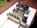
i'm working on h-bridge with two ir2110 and ir3205 mosfet's.
30Khz PWM comes from atmega168 (gradually rising form 0 to 200 and back to zero in 1.5 sec)
H bridge runs a brushed DC 18v 1ohm motor form cordless drill (non loaded)
I used this design to start:
http://www.eeweb.com/project/circuit_projects/pwm-dc-motor-controller-using-mosfets-and-ir2110-h-bridge-driver
and modified it when i found this: (figure 8)
http://tahmidmc.blogspot.com/2013/01/using-high-low-side-driver-ir2110-with.html
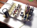
Designs are same except second has lower values of caps, superfast diodes and pull down resistors form gate to source, and bunch of decoupling caps.
The reason i switched to second design is that previous missed the gate to source resistors. After few minutes mosfets opened themselves and short circuited the battery(2*12V 45Ah in series) making small fire. Board was scrapped but the mosfets were intact.
Also values of the charge capacitors seemed too high(100uF) in the first design. (for 30khz PWM)
I retained bypass schotky didoes on the second design.
I tested the driver part of the scheme and it has valid outputs. Everything is connected correctly. I separated(different PCB) the controller form the drivers and the drivers from the H-bridge. It is pretty clean design. I have ceramic 100nf decoupling everywhere. Everything is grounded to a common household ground. I use anti static band all the time.
I used 7812 for 12V charge pump, 7805 for 5V input
When i switched to second design i got this problem.
PROBLEM: when the controller applies the pwm and tries to run the motor, short circuit occurs trough one side of the H bridge and lower schottky diode burns and after that the motor starts.
I will test in the morning again with the 100uF charge caps but..
I'm asking you guys if someone can confirm this design as valid and maybe suggest why the problem occurs?
http://4.bp.blogspot.com/-Lld4HStSKlw/UPvns0ckrZI/AAAAAAAAAaA/RFqfmsuv7bM/s1600/IR2110+-+7.png
Any help will be appreciated.
Regards
i'm working on h-bridge with two ir2110 and ir3205 mosfet's.
30Khz PWM comes from atmega168 (gradually rising form 0 to 200 and back to zero in 1.5 sec)
H bridge runs a brushed DC 18v 1ohm motor form cordless drill (non loaded)
I used this design to start:
http://www.eeweb.com/project/circuit_projects/pwm-dc-motor-controller-using-mosfets-and-ir2110-h-bridge-driver
and modified it when i found this: (figure 8)
http://tahmidmc.blogspot.com/2013/01/using-high-low-side-driver-ir2110-with.html
Designs are same except second has lower values of caps, superfast diodes and pull down resistors form gate to source, and bunch of decoupling caps.
The reason i switched to second design is that previous missed the gate to source resistors. After few minutes mosfets opened themselves and short circuited the battery(2*12V 45Ah in series) making small fire. Board was scrapped but the mosfets were intact.
Also values of the charge capacitors seemed too high(100uF) in the first design. (for 30khz PWM)
I retained bypass schotky didoes on the second design.
I tested the driver part of the scheme and it has valid outputs. Everything is connected correctly. I separated(different PCB) the controller form the drivers and the drivers from the H-bridge. It is pretty clean design. I have ceramic 100nf decoupling everywhere. Everything is grounded to a common household ground. I use anti static band all the time.
I used 7812 for 12V charge pump, 7805 for 5V input
When i switched to second design i got this problem.
PROBLEM: when the controller applies the pwm and tries to run the motor, short circuit occurs trough one side of the H bridge and lower schottky diode burns and after that the motor starts.
I will test in the morning again with the 100uF charge caps but..
I'm asking you guys if someone can confirm this design as valid and maybe suggest why the problem occurs?
http://4.bp.blogspot.com/-Lld4HStSKlw/UPvns0ckrZI/AAAAAAAAAaA/RFqfmsuv7bM/s1600/IR2110+-+7.png
Any help will be appreciated.
Regards
Last edited by a moderator:


 I managed to make it latch up easily.