MOSFET Gate Instability? Diagnosing Unexpected Piezo Behavior

Thread Starter

DOOBALOO

Joined Apr 4, 2023
9
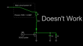
When S1 is closed, it connects to the main 3V supply. However, when this happens, the piezo element starts buzzing loudly—even though the MOSFET gate remains closed. Why is this happening?

Interestingly, when a 1k resistor is placed in series with the inductor (not the 32Ω resistor in the schematic, but the inductor’s own resistance), the issue disappears. In this case, when the 7555 output is high and voltage reaches the gate, the piezo remains quiet or muffled.

On the other hand, when S2 is closed, the piezo does not buzz and functions correctly—but only when using an external power source that is isolated from the main supply. In this setup, when the 7555 output is high and voltage is applied to the gate, I get loud and clear clicks from the piezo.

The Question:
How can I prevent the piezo from buzzing when connected to the main power supply, without needing a separate isolated power source?

I’d rather not use transformers or optocouplers due to power consumption concerns. Could there be an issue in the circuit causing the piezo or the MOSFET gate to oscillate unexpectedly?


Circuit.pngCircuit.png
 

ronsimpson

Joined Oct 7, 2019
4,646
What is the 3V supplies. Many of the small batteries will not handle large currents.
There are two different versions of that 7555. The older ones only worked down to 3V while the newer ones down to 2V. You might have the supply dropping too low for a short time.
Many MOSFETs do not work well with a 3V Gate to Source voltage. You might need to pick a low gate voltage version of the part.

My first three thoughts. RonS.
 

Thread Starter

DOOBALOO

Joined Apr 4, 2023
9
What is the 3V supplies. Many of the small batteries will not handle large currents.
There are two different versions of that 7555. The older ones only worked down to 3V while the newer ones down to 2V. You might have the supply dropping too low for a short time.
Many MOSFETs do not work well with a 3V Gate to Source voltage. You might need to pick a low gate voltage version of the part.

My first three thoughts. RonS.
I appreciate your help. I'm using the new 2V-18V 7555, along with a DMN62D0U MOSFET, which has a gate threshold voltage ranging from 0.5V to 1V. And I'm using 2x AA batteries
 

Thread Starter

DOOBALOO

Joined Apr 4, 2023
9
Why have you got the piezo element in parallel with the MOSFET? What are you trying to achieve?
Tried it in series too, but it didn't do anything, only works in parallel.
What are you trying to achieve?
When the mosfet is open, the inductor starts building up current and the remaining charge in the transducer is removed to increase voltage swing across it (electrically they behave like capacitors, so they can hold some charge). When the mosfet closes, the energy that the inductor had at that time, is transferred into piezo element and it clicks. I'm basically stepping up the voltage to hear louder clicks because with only 3 volts its quiet. But like stated before it doesn't do it while connected to the 3V main. only when using another power source isolated from main.
 

Irving

Joined Jan 30, 2016
4,996
OK, & What is the purpose of the opamp driving the monostable 7555?

When the mosfet closes, the energy that the inductor had at that time, is transferred into piezo element and it clicks.
No, when the MOSFET is ON, energy is stored in the inductor. When the MOSFET goes OFF, that energy is transferred to the piezo... the back EMF from the inductor raises the drain voltage of the MOSFET (& therefore the piezo) to around 60v

1749405901727.png
 

Thread Starter

DOOBALOO

Joined Apr 4, 2023
9
OK, & What is the purpose of the opamp driving the monostable 7555?


No, when the MOSFET is ON, energy is stored in the inductor. When the MOSFET goes OFF, that energy is transferred to the piezo... the back EMF from the inductor raises the drain voltage of the MOSFET (& therefore the piezo) to around 60v

View attachment 350725
You are totally right i got it mixed up, but it still doesn't answer my question of why its tarts buzzing when i connect it to the main power source. only when i use another power source isolated from the main source it starts working properly.1749450272556.png.
Works completely fine.

1749450439158.png
Starts buzzing as soon as VCC is applied on the inductor.
 

Attachments

Thread Starter

DOOBALOO

Joined Apr 4, 2023
9
Put a 'scope on the main power rail in scenario 2 above.... what do you see?
It looks like I've pinpointed the issue. Adding a large capacitor to the power rail seems to have stabilized everything. I suspect the batteries aren't supplying consistent power, when the gate is open and the piezo click causes the comparator’s reference voltage to drop, leading to oscillation. However, with a large capacitor in place, the system runs smoothly unless I get too close to the comparator’s reference voltage.

It’s strange because the clicker circuit—comprising the inductor, MOSFET, and piezo—only draws around 3mA to 4mA when active. I would have expected the batteries to be stable enough to handle that load without issue.
 

Irving

Joined Jan 30, 2016
4,996
That's what I expected you'd see... AA batteries, particularly when not brand new, have a quite high internal impedance to transient currents. A large capacitor is the solution as you discovered (in fact this is generally a good option for all battery powered circuits). If you replace 2 x AA with a single Lipo cell you won't see the issue because they have a very low transient impedance.

BTW, when the MOSFET is ON the current draw is far more than 4mA, its more like 65mA peak and with a 50% duty cycle the RMS value is 30mA - that's a lot to ask from an AA cell.

1749486650745.png
 

Thread Starter

DOOBALOO

Joined Apr 4, 2023
9
That's what I expected you'd see... AA batteries, particularly when not brand new, have a quite high internal impedance to transient currents. A large capacitor is the solution as you discovered (in fact this is generally a good option for all battery powered circuits). If you replace 2 x AA with a single Lipo cell you won't see the issue because they have a very low transient impedance.

BTW, when the MOSFET is ON the current draw is far more than 4mA, its more like 65mA peak and with a 50% duty cycle the RMS value is 30mA - that's a lot to ask from an AA cell.

View attachment 350761
That seems like quite a high current for such a simple circuit—perhaps I misjudged it. Either way, I really appreciate your response and the helpful answers.
Do you think there’s a way to reduce the current while maintaining the same functionality? I know adding a resistor in series is an option, but it does lower the piezo’s loudness.
 

BobTPH

Joined Jun 5, 2013
11,463
That seems like quite a high current for such a simple circuit—perhaps I misjudged it
What an odd thing to say. How much current would you expect if you shorted the battery terminals with a wire? That’s as simple a circuit as you can make.
 

Irving

Joined Jan 30, 2016
4,996
That seems like quite a high current for such a simple circuit—perhaps I misjudged it. Either way, I really appreciate your response and the helpful answers.
Do you think there’s a way to reduce the current while maintaining the same functionality? I know adding a resistor in series is an option, but it does lower the piezo’s loudness.
How did you get to 4mA? Did you measure it or guess it?

Reducing the current and getting the same result isn't possible - laws of physics, etc. - however shortening the pulse length from 500uS to 250uS at the same 1kHz frequency would not change peak current but would reduce the RMS current to 30mA from 43mA (I misquoted it as 30mA before but its 43mA at 500uS pulse width as shown in the sim above). It may not reduce the loudness too much subjectively - try it.
 

Thread Starter

DOOBALOO

Joined Apr 4, 2023
9
How did you get to 4mA? Did you measure it or guess it?

Reducing the current and getting the same result isn't possible - laws of physics, etc. - however shortening the pulse length from 500uS to 250uS at the same 1kHz frequency would not change peak current but would reduce the RMS current to 30mA from 43mA (I misquoted it as 30mA before but its 43mA at 500uS pulse width as shown in the sim above). It may not reduce the loudness too much subjectively - try it.
Oops, I misread it, it was 40mA, not 4mA! But I think I’ve found a way to make the circuit more power-efficient. I came across this formula, and it seems that using a higher-value inductor will help prevent the circuit from reaching the inductor’s peak current.

The steady-state current for your inductor would be:

I_max = V / R = 3V / 72Ω = 41.67mA

Using the transient response formula:

I(t) = I_max (1 - e^(-t / τ))

where the time constant is:

τ = L / R = 100mH / 72Ω = 1.39ms

For a 500µs pulse:

I(500µs) = 41.67mA × (1 - e^(-500µs / 1.39ms))

Approximating:

I(500µs) ≈ 41.67mA × (1 - e^(-0.36))
I(500µs) ≈ 41.67mA × 0.3 ≈ 12.5mA

And if that's not enough i can decrease the pulse duration to 300us or 200us.
200us should be around 5mA-6mA.
 

Irving

Joined Jan 30, 2016
4,996
Nice try, but reducing the inductor current just reduces the energy transferred to the piezo which is going to reduce the volume. The sound output depends on the flexation force which is proportional to the charge imparted, and to the acoustic situation (ie how the air pressure around the piezo reacts to its flexing). If you excite the piezo at or near its resonant frequency you will get more sound output. Do you have any specs on the piezo you are using or links to manufacturer and/or datasheet?
 

Thread Starter

DOOBALOO

Joined Apr 4, 2023
9
Nice try, but reducing the inductor current just reduces the energy transferred to the piezo which is going to reduce the volume. The sound output depends on the flexation force which is proportional to the charge imparted, and to the acoustic situation (ie how the air pressure around the piezo reacts to its flexing). If you excite the piezo at or near its resonant frequency you will get more sound output. Do you have any specs on the piezo you are using or links to manufacturer and/or datasheet?
Yes, but I'm aiming to strike a balance between loud and excessively loud. It's generally best practice to keep the voltage close to the piezo's rated voltage, even though it can tolerate it.
 
Top