Mosfet Gate Driver Circuit

Thread Starter

SNEHARAMTEKE

Joined May 25, 2017
3
Hello,

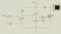
I am working on a Totem Pole low side gate driver circuit that gets its input (i.e. 5 V square wave) from a microcontroller. The Power Mosfet used is IRF540N. The circuit works well at 1KHz. But when the frequency is increased to 20KHz, I am unable to get a square waveform at the drain. The waveform that is visible is triangular in shape. Please help me out in debugging the circuit. Thanks!
 

OBW0549

Joined Mar 2, 2015
3,566
We can't help you at all if you don't post a circuit diagram. Post a schematic, complete with all components, connections and component values, and we might be able to help.
 

OBW0549

Joined Mar 2, 2015
3,566
I think what you're seeing is due to Q3's load resistor, R5, being so high. Try changing it to 100Ω and see what you get. Otherwise, the circuit looks OK.
 

MrAl

Joined Jun 17, 2014
11,457
What is the purpose of R2 and D3?
Hi,

Asymmetrical drive for the mosfet.

However, the 500 ohm resistor looks too big to properly drive a mosfet. 10 ohms is more typical.
That 10k ohm load looks strange too, i think a load would be a lower value than that.
 

shortbus

Joined Sep 30, 2009
10,045
Another one of those threads that make no sense to me. A single 8 pin mosfet driver seems a lot simpler to me than 3 transistors and a handful of resistors. Takes up less board space too.
 

crutschow

Joined Mar 14, 2008
34,408
Asymmetrical drive for the mosfet.

However, the 500 ohm resistor looks too big to properly drive a mosfet. 10 ohms is more typical.
That 10k ohm load looks strange too, i think a load would be a lower value than that.
Okay, that could be used to delay the MOSFET turn-on and prevent shoot-through conduction in a bridge circuit.
In that case the resistor is using the gate capacitance to provide a turn-on delay.
So it's value would depend upon how much delay you need and the particular MOSFET gate capacitance.
Thus 500Ω could be too large, too small, or just right. ;)
 

Thread Starter

SNEHARAMTEKE

Joined May 25, 2017
3
Hello Sir,
I changed the resistance value of R5 to 100 ohms and the circuit is working absolutely fine giving correct results. Thank you so much for your advice.
 
Top