MOSFET fail short - searching for cause

Thread Starter

Marcel DaJanchar

Joined Sep 9, 2015
32
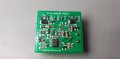
Sorry for double post, but I just saw one difference between my faulty and one fresh circuit. I have attached images of these two circuits. Take a look at these FETs. They have different font style on them. Should this be enough to say that faulty circuit had counterfeit on it?
 

Attachments

dl324

Joined Mar 30, 2015
16,922
There isn't enough resolution in any of the photos to tell.

Counterfeit parts often have a blacktop coating to cover the effects of sandblasting the old part numbers and then they remark. The top surface of pins also show pitting.

The texture of the package should be similar on top and bottom. 3 pin SMT devices will be difficult to see because there's not much real estate.
 

dl324

Joined Mar 30, 2015
16,922
FETs were bought on eBay yes.
These days, I wouldn't buy semiconductors on eBay unless it looked like it was an odd lot. People who have stores where they buy in bulk and repackage could be selling counterfeit or substandard (reject) parts without even knowing.

As I recall, the second picture I posted for eBay listings didn't ship from China. Shipping from China usually means it's counterfeit; though I'm seeing more counterfeit product shipped from Cambodia. I see listings for obviously counterfeit parts on eBay all the time now and I sometimes take the time to report them to eBay as illegal activity.
 

Thread Starter

Marcel DaJanchar

Joined Sep 9, 2015
32
Okay, today I have installed new circuit to my car (circuit is on the yesterdays pictures marked as 'fresh circuit'). Circuit was fully functional whole day, until I cranked the car at the gas station. Both of FET stayed enabled. So now, I suspect car cranking spikes. Is there any common protection against these spikes?
 

Thread Starter

Marcel DaJanchar

Joined Sep 9, 2015
32
Is it common in automotive electronics to implement TVS diode or varistors? If so, where do I put it?

Can the circuit be redesigned with capacitive power supply so the whole circuit is ground-isolated from car chasis? So even if spike happen, whole circuit's voltage potential would rise and no overvoltage would happen on gate pin of MOSFETs (refering to circuit's ground). Just thinking out loud... Correct me if I'm wrong. I hope you understand my questions. Thanks.
 

dl324

Joined Mar 30, 2015
16,922
Is it common in automotive electronics to implement TVS diode or varistors? If so, where do I put it?
Put it across the 12V power rail.

Can the circuit be redesigned with capacitive power supply so the whole circuit is ground-isolated from car chasis? So even if spike happen, whole circuit's voltage potential would rise and no overvoltage would happen on gate pin of MOSFETs (refering to circuit's ground).
Don't see how you could. The MOSFET can't switch 12V to the lights if the circuit's ground isn't connected to the vehicle.
 

Thread Starter

Marcel DaJanchar

Joined Sep 9, 2015
32
I will try with a TVS, but this will take few weeks before I get them.

Another question: What happen if I exceed Vds of the MOSFET? As I read, it acts like a zener (does this mean internal diode?), so the current will flow and thus, the FET will heat up very fast. Can few miliseconds of overvoltage condition be fatal for FET?

Here, I attached a graph of which spikes can occur on the car battery (= my circuit's power supply).


In the AO3401's datasheet, maximum Vsd is 30V. We can see that Vsd can easily be exceeded in load dump condition. Would TVS across source-drain pins help to protect maximum Vsd not being exceeded? Can I use higher power rated zener instead of TVS? Is there an easy was to protect my circuit against reverse voltage? Thanks.
 

LowQCab

Joined Nov 6, 2012
4,072
You guys are missing the elephant in the room.
Incandescent Light Bulbs have a MASSIVE spike in current when the filament is cold (dark).
They may be rated for ~2 amps, but when they first turn on, they spike to around ~10 amps.

The next problem is that you may not be putting the FET into full saturation.
I have not looked at the specs for your FET, but I can tell you it's risky to use SMD
devices, WITH NO HEAT SINK, and then only turn it on half way.
Why do you have a voltage divider on the Gate ??
When the car's alternator is not keeping up with the load......
( headlights on, AC Blower on, Brake Lights on, Engine at Idle Speed)
the battery voltage can easily drop to less than ~12 volts, cut that in half with your voltage
divider and you are charging the Gate of the FET with only ~6 volts.
This voltage may be dropping even more than that,
I would be willing to bet that you are feeding this board with an 18 gauge wire,
which will have a SIGNIFICANT voltage drop when the lamp first turns "on", and is trying to pull ~10 amps,
this will further reduce the Gate drive to the FET, and make it turn on "part way" and SLOWLY,
generating a big heat "spike" in the process, and extending the TIME that the spike will last.
Power supply "voltage-sag" can be a very significant factor in automotive applications.
(the average heat "may" be very low, but there is such a thing as a heat "spike" that can do damage)
Look at the spec sheet for the FET you want to use and see what the "Rds" is at ~5 to ~6 volts on the Gate.
Then do voltage drop calculations AT TEN AMPS, then calculate how many
WATTS of power you are trying to dissipate out of that microscopic SMD device.
The spec sheet will tell you how many MILLI WATTS that particular SMD package can dissipate.
BUT, you should be running a TO-220 packaged device anyway,
hand soldered SMD is NOT going to be reliable as far as heat dissipation goes.
A TO-220 package is easy to mount to a small heat sink with a screw, and can
withstand FAR MORE ABUSE than an SMD package.
Here is the FET that I would choose for your application.........
https://www.digikey.com/product-detail/en/renesas-electronics-america/2SJ649-AZ/2SJ649-AZ-ND/2764204
They are ~$2.oo each, and you will have to screw them to a small chunk of aluminum or
an old CPU heat sink from a dead computer.
Get rid of the voltage divider at the Gate, the Gate on this device is rated for +- 20v, so SLAM IT with
a full 12 volts, (ground), so that it never has to operate "half-way-on",
it needs to be either FULL ON, or, FULL OFF, never in between.
Do not worry too much about protecting the gate from too much current,
you are not switching it at at high frequencies, so that's not as important,
you should, however, have 16-volt Zener, or TVS, protection for the whole circuit board,
and a big fat filter capacitor (3,300uf) on the power feed to the board, bigger is better.
This will eliminate any "dirty power/spike" problems that might happen.

The second option, is to change all of your light bulbs to LEDs.
 

Thread Starter

Marcel DaJanchar

Joined Sep 9, 2015
32
You guys are missing the elephant in the room.
Incandescent Light Bulbs have a MASSIVE spike in current when the filament is cold (dark).
They may be rated for ~2 amps, but when they first turn on, they spike to around ~10 amps.

The next problem is that you may not be putting the FET into full saturation.
I have not looked at the specs for your FET, but I can tell you it's risky to use SMD
devices, WITH NO HEAT SINK, and then only turn it on half way.
Why do you have a voltage divider on the Gate ??
When the car's alternator is not keeping up with the load......
( headlights on, AC Blower on, Brake Lights on, Engine at Idle Speed)
the battery voltage can easily drop to less than ~12 volts, cut that in half with your voltage
divider and you are charging the Gate of the FET with only ~6 volts.
This voltage may be dropping even more than that,
I would be willing to bet that you are feeding this board with an 18 gauge wire,
which will have a SIGNIFICANT voltage drop when the lamp first turns "on", and is trying to pull ~10 amps,
this will further reduce the Gate drive to the FET, and make it turn on "part way" and SLOWLY,
generating a big heat "spike" in the process, and extending the TIME that the spike will last.
Power supply "voltage-sag" can be a very significant factor in automotive applications.
(the average heat "may" be very low, but there is such a thing as a heat "spike" that can do damage)
Look at the spec sheet for the FET you want to use and see what the "Rds" is at ~5 to ~6 volts on the Gate.
Then do voltage drop calculations AT TEN AMPS, then calculate how many
WATTS of power you are trying to dissipate out of that microscopic SMD device.
The spec sheet will tell you how many MILLI WATTS that particular SMD package can dissipate.
BUT, you should be running a TO-220 packaged device anyway,
hand soldered SMD is NOT going to be reliable as far as heat dissipation goes.
A TO-220 package is easy to mount to a small heat sink with a screw, and can
withstand FAR MORE ABUSE than an SMD package.
Here is the FET that I would choose for your application.........
https://www.digikey.com/product-detail/en/renesas-electronics-america/2SJ649-AZ/2SJ649-AZ-ND/2764204
They are ~$2.oo each, and you will have to screw them to a small chunk of aluminum or
an old CPU heat sink from a dead computer.
Get rid of the voltage divider at the Gate, the Gate on this device is rated for +- 20v, so SLAM IT with
a full 12 volts, (ground), so that it never has to operate "half-way-on",
it needs to be either FULL ON, or, FULL OFF, never in between.
Do not worry too much about protecting the gate from too much current,
you are not switching it at at high frequencies, so that's not as important,
you should, however, have 16-volt Zener, or TVS, protection for the whole circuit board,
and a big fat filter capacitor (3,300uf) on the power feed to the board, bigger is better.
This will eliminate any "dirty power/spike" problems that might happen.

The second option, is to change all of your light bulbs to LEDs.
Hello @LowQCab!

If you look at my schematics and do some simple calculations, you can clearly see that FETs are put into full saturation. Resistor divider at gate is there to prevent exceeding Vgs of the FET, which is rated +12V max!
The resistance of the source-drain is very low, so I calculated that I do not need heatsink for my desired load (2A).

P = I*I*R = 2A * 2A * 0.06ohm= 0.24W

If we look at the FET's datasheet under thermal characteristic that the package will be heated 80°C every 1W. So if we disippate 0.24W and multiply it with 80 we get temperature rise of 20°C. That is not critical for my circuit and also this is not the cause of my problem.

Car's alternator is keeping with the load and will not drop below 12v at any point (ok maybe for few miliseconds). It was designed that way, so your car battery is charging even will all loads connected together. As I said, the FET needs at least 4.5V to have drain-source resistance lower than 0.06ohms.

I dont know how much 18 gauge wire is because I use mm2 but I ensure you that wire is thick enough to handle needed current.

I have used TO220 package, but for my purpose I need small circuit and based on calculations, SOT23 must handle this current. I have also added thermal pads below so overheating is not the problem here.

Again, I cannot 'slam it' with 12V because that way the FET will say goodbye in short time. The driver NPN serves that rise and fall time are minimalistic (therefore R3 and R8 have lower resistance).

I think that frequency does not matter at gate protection, because we must look for rise and fall time of Vgs to be minimal. On my osciloscope, rise and fall time are in desired ranges.

As for the 'big fat capacitor', if the spike occurs, you store that energy in that cap. You only postpone the fatality (maybe I'm wrong here?).

Sadly, I cannot change all bulbs to LED. This circuit must work with both loads.
 

shortbus

Joined Sep 30, 2009
10,045
Why not use a mosfet with the proper gate voltage for the circuit voltage? Or add a voltage regulator to the gate drive, that would be better than a voltage divider.
 

Thread Starter

Marcel DaJanchar

Joined Sep 9, 2015
32
I use zener diode as voltage regulator at gate drive.

Today, I've received TVS diodes. Where do I solder it - between VCC and GND or between gate and source of the output MOSFETS? Which option is preffered?
 

MisterBill2

Joined Jan 23, 2018
18,519
to protect the other output device when one short circuits you must have a series diode in each gate drive line, and then a separate gate to source pull-down resistor so that it will switch off when the drive is removed.
AND FET switches will tend to get very hot if they are not biased into full conduction. So a slight failure in the drive circuit can easily cause destruction by only driving it into the linear mode, not to full saturation.
Why didn't anybody else think of that???
 

Thread Starter

Marcel DaJanchar

Joined Sep 9, 2015
32
Hello! Little update.

Today I've started my car on cold winter morning. Guess what, the FETs are damaged again (with TVS diode applied between GND and VCC). We can isolate the cause of this problem to car cranking. Is there any power supply passive filter available to get rid of nasty spikes? I want to keep this project on low budget.
 

MisterBill2

Joined Jan 23, 2018
18,519
One cheating trick could be to feed the circuit from the accessory line so that it would be disconnected during cranking. If it works that way in your vehicle. Some vehicles have an accessory feed that does not come up right away, while with some others it stays on even during cranking. BUT if it switches off that might be an easy work-around. A second option would be to add a spike and noise filter with an inductor and then a bypass capacitor. To avoid expense you would need to wind the inductor your self, using a scrapped transformer core. It would be expensive to purchase one, though so I am only recommending that if you can make one cheaply. I am not sure how much current needs to pass through the FETs , if that was mentioned I may have missed it. That will have a big influence on the spike limiting circuit.
 

MisterBill2

Joined Jan 23, 2018
18,519
@MisterBill2 I have wired it to accessory line, but that is only the power supply part of the circuit. FETs are wired on blinker bulbs all the time. I use one bulb 12V21W per FET.
OK, then it might be the spikes on the Vcc lines feeding the FET devices.And I am thinking possibly an issue with the connection arrangement with the connections of the TVS diodes. The amount of resistance that can go into the power supply lines is quite limited because those bulbs draw almost 2 amps when lighted. Thus my additional suggestion would not work. IT may be that you need transistors rated for 150, or even 200, volts, and several amps, with a peak current rating of possibly 20 amps. Extreme indeed, but it seems that there are bigger spikes causing problems.
 
Top