MOSFET driver needs a pull-down resistor?

Thread Starter

waulu

Joined Dec 23, 2016
62
Hello,

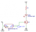
I need to control a high current load, for that I am using a microcontroller, the MOSFET Driver MIC5018 and the MOSFET HUF75344P3.

Right now, I am just making small tests and I am using resistors and a LED to test the circuit, I have attached the schematic.

My problem is that the LED doesn’t turn off, I need to add a pull-down resistor bigger than 200kOhms on the gate, if it’s lower it will keep the LED always off. Another problem is that when I use a 200k ohms resistor, the VGS will lower too much to 2.7 Volts. If I use the multimeter as resistor (10 Mohms), the VGS will be 7.8V, I think that's enough to obtain a current of 10A in the future.

Shouldn't the driver MIC5018 be able to handle this? Shouldn't it be able to pull-down the gate?

Thank you in advance
 

Attachments

SteveSh

Joined Nov 5, 2019
109
I don't know why you would need a pull-down resistor on the gate if the driver is working properly. The driver has an active low FET on its output which should keep the gate of the external MOSFET very close to GND when turned off, though I do not see a spec for the low voltage on the G output on the data sheet.
 

cmartinez

Joined Jan 17, 2007
8,218
Put a high value pull down resistor at the mosfet's gate, something like 47K. This is out of caution for circuit startup.

But on the other hand, the driver should be able pull the gate down on its own, according to the datasheet. Also, keep in mind that that driver in particular is designed for high-side applications.

On the other hand, that mosfet in particular should work just fine with 5V delivered from an MCU's pin triggering its gate, without using a driver... as long as you don't need to switch it at a mid to high frequency,
 

Thread Starter

waulu

Joined Dec 23, 2016
62
Any reason you are using a High side driver?
Why not drive from the Micro controller and a logic level Mosfet.?
Max.
I had these components but I never used them. According to the datasheet it operates in low- and high-side configurations so I thought was ok. Honestly, I wasn't aware of those logic-level transistors, but I already I found one that seems to fit my project,
https://www.mouser.fr/datasheet/2/308/FDD8896-1300393.pdf
I don't know why you would need a pull-down resistor on the gate if the driver is working properly. The driver has an active low FET on its output which should keep the gate of the external MOSFET very close to GND when turned off, though I do not see a spec for the low voltage on the G output on the data sheet.
I don't understand your statement. It's not working properly, without the pull-down resistor the LED doesn't turn off.

Put a high value pull down resistor at the mosfet's gate, something like 47K. This is out of caution for circuit startup.

But on the other hand, the driver should be able pull the gate down on its own, according to the datasheet. Also, keep in mind that that driver in particular is designed for high-side applications.

On the other hand, that mosfet in particular should work just fine with 5V delivered from an MCU's pin triggering its gate, without using a driver... as long as you don't need to switch it at a mid to high frequency,
With a resistor of 47K the driver won't be able to turn on the MOSFET, the resistor needs to be bigger than 200K. The signal from the uC is 3.3V, with that I am afraid that the MOSFET won't be able to deliver 10 A.

Ok so the logical solution would be to change to a transistor that's compatible with 3.3 V. But now for curiosity I would like to know why this is happening so I can learn a little bit more.
 

SteveSh

Joined Nov 5, 2019
109
I had these components but I never used them. According to the datasheet it operates in low- and high-side configurations so I thought was ok. Honestly, I wasn't aware of those logic-level transistors, but I already I found one that seems to fit my project,
https://www.mouser.fr/datasheet/2/308/FDD8896-1300393.pdf

I don't understand your statement. It's not working properly, without the pull-down resistor the LED doesn't turn off.
My statement has to do with understanding why the resistor works. Like I said, the output of the MOSFET driver should be able to pull the gate down to within a handful of millivolts of GND. That should turn the MOSFET off. If the MOSFET driver is working correctly, the resistor to GND should have no affect. Just throwing resistors at a problem without understanding why they work may be useful as a troubleshooting technique. But not understanding why they fix the problem is a recipe for other problems down the road.
 

TeeKay6

Joined Apr 20, 2019
573
I had these components but I never used them. According to the datasheet it operates in low- and high-side configurations so I thought was ok. Honestly, I wasn't aware of those logic-level transistors, but I already I found one that seems to fit my project,
https://www.mouser.fr/datasheet/2/308/FDD8896-1300393.pdf

I don't understand your statement. It's not working properly, without the pull-down resistor the LED doesn't turn off.


With a resistor of 47K the driver won't be able to turn on the MOSFET, the resistor needs to be bigger than 200K. The signal from the uC is 3.3V, with that I am afraid that the MOSFET won't be able to deliver 10 A.

Ok so the logical solution would be to change to a transistor that's compatible with 3.3 V. But now for curiosity I would like to know why this is happening so I can learn a little bit more.
The datasheet states that the output pin will rise to a min of 7.1V with a 3V supply; higher with a 3.3V supply. The device has a built-in voltage boost. Reiterating what others have said and what the datasheet shows, no resistor should be needed or used from the MOSFET gate to ground. On the other hand, @cmartinez is correct that the device G output is undefined when the supply voltage is very low (<2V???), but even a 1meg resistor to ground should turn the MOSFET off. Also as others have noted, the simpler solution is to simply drive a low-threshold MOSFET directly from a microcontroller output pin.
 

cmartinez

Joined Jan 17, 2007
8,218
The datasheet states that the output pin will rise to a min of 7.1V with a 3V supply; higher with a 3.3V supply. The device has a built-in voltage boost. Reiterating what others have said and what the datasheet shows, no resistor should be needed or used from the MOSFET gate to ground. On the other hand, @cmartinez is correct that the device G output is undefined when the supply voltage is very low (<2V???), but even a 1meg resistor to ground should turn the MOSFET off. Also as others have noted, the simpler solution is to simply drive a low-threshold MOSFET directly from a microcontroller output pin.
Agreed 100%
 

cmartinez

Joined Jan 17, 2007
8,218
If it's any help, I've been using the DMN1019USN at the low side and the DMP2066LSN at the high side of an H-Bridge switch, driving them directly from a 3.3V MCU without a problem. One thing that you could do, is use those little Fets connected as a totem pole to drive your nFet's gate, assuming you have a 5V (preferably something above 10V) source to drive that gate with.
 
Top