MOSFET chopper controlled by 8051

Thread Starter

Anirban Raha

Joined Dec 4, 2013
70
i tried putting two 330 ohm resistors...the 12V supply is dropping to 6V at the MCU circuit...but unfortunately i guess the microcontroller's impeadance is varying with its operation and thus the supply voltage is also varying...am i correct? or is this the correct way to acheive 5V out of a 12V battery? my mcu got fried btw...dnt knw how...
 

JohnInTX

Joined Jun 26, 2012
4,787
but unfortunately i guess the microcontroller's impeadance is varying with its operation and thus the supply voltage is also varying...am i correct?
Yes, you are correct. A good way to do it would be to power the processor with an LM7805 (LM340T-5) linear regulator with suitable heat sink. A better but more complex way would be to use one of the simple-switcher setups. A switcher won't waste the battery power like the linear regulator will. To regulate, the linear one dissipates the extra power as heat - wasting it, the switcher turns off/on at high frequency to maintain a uniform output. The link has a calculator that figures things out for you. Nice.

Two resistors, as you have found, would be a bad way to power the uC. Sorry.
 

Thread Starter

Anirban Raha

Joined Dec 4, 2013
70
The circuit was working well with two seperate power supplies...but now I'm experimenting with L7805...and the circuit is not working well...firstly...the output of the mosfet driver is following the programming when the motor is not connected...problem starts when i connect it...when i connect the motor...the driver output is somehow being forced to almost zero...or something of that sort...and the motor is barely rotating...is it because i was unable to decouple the circuits properly? I am doing this on a breadboard and the MCU is rather close to driver circuit because of space restrictions. could that be the reason? the grounds are connected at a single point close to the driver and the wire connecting the point is longer than other wires...and after trying out this circuit for a few times with the motor...the output of the IR2121 is stuck at zero...even if I remove the motor...I should also mention that the circuit is behaving strangely at times...even touching wires with multimeter leads to check the voltage is starting the motor at times...I'm absoutely confused!!! Need your help!!!
 

Thread Starter

Anirban Raha

Joined Dec 4, 2013
70
BTW...that simple switcher link that you gave in the previous post seems to have been removed...could you provide that link again please?
 

JohnInTX

Joined Jun 26, 2012
4,787
Here is the link on TI's simple switchers.

Can you post a sketch of your circuit and the code? Its hard to tell what's going on without it.

well...firstly...the output of the mosfet driver is following the programming when the motor is not connected...problem starts when i connect it...when i connect the motor...the driver output is somehow being forced to almost zero...or something of that sort...and the motor is barely rotating...is it because i was unable to decouple the circuits properly?
Are you sure you have enough capacity in your power supply? Adequate wire sizes. IIRC, you are going for 8A on the motors. That's a bunch.
 

Thread Starter

Anirban Raha

Joined Dec 4, 2013
70
I'm sure the battery packs enough power...It can power four of these motors at 12V simultaneously :cool:(I have tested it). Ratings say that it can provide about 113A continuously.
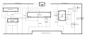
I have attached the entire control board schematic. This is exactly what my circuit looks like on the bread-board. Is this good enough? Or do I need more capacitors(or something else)?
As for the code...I've used plain old delay loops...I don't know how to use the timers :D. Could that also be a factor? I mean..it works well with LEDs(gradually brightens up and dims out). I guess timers will simplify this program...but I don't know the code for that...The program increases voltage on pin P2.0 when p0.0 is 0 and p0.1 is 1 and vice versa; and holds the current voltage when both pins are either high or low. Here is the code:

Rich (BB code):
#include<reg52.h>
#include<stdio.h>

void delay(void);
sbit motor_pin_1 = P2^0;
sbit switch_st=P1^1;
sbit switch_st2=P1^0;    
bit x;
bit y;

void hold(int v,int l)
{
    int i;
    do
    {
        x=switch_st;
        y=switch_st2;
        motor_pin_1=1;
        for(i=0;i<=v;i++)
    {
        delay();
    }
    motor_pin_1=0;
    for(i=l;i>=v;i--)
    {
        delay();
    }
    }while((x==0&&y==0)||(x==1&&y==1));
}
int increase(int l,int v)
{
    int c=v,i;
    do
    {
        x=switch_st;
        y=switch_st2;
        motor_pin_1=1;
        for(i=0;i<=c;i++)
    {
        delay();
    }
    motor_pin_1=0;
    for(i=l;i>=c;i--)
    {
        delay();
    }
        if(c<=500)
          c++;
    }while(x==1&&y==0);
    return c;
}    
int decrease(int l,int v)
{
    int c=v,i;
    do
    {
        y=switch_st2;
        x=switch_st;
        motor_pin_1=1;
        for(i=0;i<=c;i++)
    {
        delay();
    }
    motor_pin_1=0;
    for(i=l;i>=c;i--)
    {
        delay();
    }
        if(c>=0)
         c--;
    }while(y==1&&x==0);
    return c;
}    
void delay()
{
  int i;
  for(i=0;i<10;i++)
  {
    }
}

void main()
{
    int v=0;
    switch_st=1;
    switch_st2=1;
    motor_pin_1=0;
    do
  {
        x=switch_st;
        y=switch_st2;
        if(x==1&&y==0)
        {    
            
            v=increase(500,v);
        }
        else
        {    
            if(y==1&&x==0)
                v=decrease(500,v);
            if((x==0&&y==0)||(x==1&&y==1))
               hold(v,500);
        }
  }while(1);
}
 

Attachments

Last edited by a moderator:

Thread Starter

Anirban Raha

Joined Dec 4, 2013
70
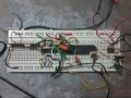
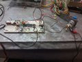
Pictures of breadboard attached...the crocodile clips that you see on the motor terminals are just meant to hold wires. :D
BTW...In the picture of the breadboard...you will see that I have used two 0.01uF ceramic capacitors with the MOSFET driver(just experimenting)...I have also used a 10uF(electrolytic) in parallel with a 100nF capacitor(just like in the schematic) without appreciable changes in results...
 

Attachments

Last edited:

Thread Starter

Anirban Raha

Joined Dec 4, 2013
70
Yup...the single, thin red and black wires...
the actual battery wires are very thick(12awg)...but those wires can't be plugged into a breadboard...so I've attached breadboard wires to them...also in this case the current is about 1.5A(5.3A is the starting current at 12V), since the motor is not loaded. I have also tried twisting these wires together...got the same results.
 
Last edited:

JohnInTX

Joined Jun 26, 2012
4,787
I think you are getting motor noise into your uC due (at least in part) to the power distribution.

The attached markup shows how I would split the supplies and add decoupling and protection for the regulator. Hope it makes sense, its a quickie.
 

Attachments

Thread Starter

Anirban Raha

Joined Dec 4, 2013
70
1. What do you mean by JPR?
2. What do you mean by tie to power line? Do you mean that I should tie the unused ground and Vcc to powerrr line? arent they internally connected?
3. Is the value of the capacitor near L7805 10.33uF or 10uF and .33uF seperately?
 

JohnInTX

Joined Jun 26, 2012
4,787
Ha! Bad penmanship.
1) Jumper. I was thinking that RST jumpered to ground would be less likely to pick up noise and reset the processor. Remove the jumper for programming or if it turns out not to be needed.

2)I didn't know if they were internally connected or not. If its a connection on a PC board, its probably OK to pick up one. If its a silicon connection like the IR driver, connect both. As a rule, I try to connect all of the Vcc/Gnd even if redundant just to be sure that someday, I don't miss one that isn't.

3)Its 10uf to 33uf Aluminum Electrolytic. Its not critical, could be several hundred if that's what you have. Its purpose is to provide a local source of power to handle surges drawn by the processor/RF module etc. The smaller ones are 1uf Tantalum and should be close to the pins of the 7805 for stability. The 7805 datasheet says .33uf on the input and .1uf ceramic on the output. Either way would work.
 

Thread Starter

Anirban Raha

Joined Dec 4, 2013
70
The whole circuit is not working. So I have broken it up into 2 parts: The micrcontroller with the motor driver and the wireless module with the motor driver.
The first circuit(without the wireless module) is working well if I follow the circuit rectified by you.:D
However the second circuit is the problem. In this circuit I have removed the microcontroller and connected the decoder IC(HT12D) directly with the IR2121 input pin. The wireless module is being powered by L7805. When I trigger the input for the first time from my remote, the motor starts running as planned. However, just when the motor starts running, the wireless module stops receiving data. It receives data again when I disconnect the motor.(I have connected an LED with the enable pin which goes off when motor starts).:(:(
I have used bypass capacitors(1 uF each) with the RF module as well as the decoder IC just as you have shown in the circuit. Should I change the capacitor to even smaller values? What else could be wrong?:confused:

P.S. I have bought a MIC4427 which seems similar to IRS44273. Its a bit cheaper than IR2121. Would it suffice?
 

JohnInTX

Joined Jun 26, 2012
4,787
I think rather than starting to change things at random you should back up and put the uC back in. Replace the motor with a simple load starting with an LED. Get that to work then increase the load using resistors parallel with the LED (and its resistor) until you get to the maximum motor current. That will test your power supply, grounding, wiring etc. up to the running current.

Then increase the current up to near the maximum of the MOSFET and run it intermittently to see if the circuit can handle the starting current of the motor - remember, the motor will pull several times its running current when starting.

Once you have that all sorted out, replace the test load with the motor. If you have problems then, you know its motor-related (noise etc.) and you can work on that.
 

Thread Starter

Anirban Raha

Joined Dec 4, 2013
70
Circuit is working with an LED in series with a 10k resistor...but could not perform the rest of the tests because my resistors are blowing...put a few 10 ohm resistors parallel to the LED(with a 1k resistor)...but the current wasnt going high enough..so i used 4 ohm resistors instead...but they blew...
More importantly i detached the circuits completely and even still the RF circuit stops receiving when the motor starts...even when i take the motor completely out of the breadboard...the enable LED flickers due to the motor running...is this electromagnetic interference? is there any possible solution to this? A seperate source for the RF isnt working either!!! any kind of contact with the driver circuit switches off the reciever circuit and even being in the viccinity of the motor is affecting reception!!! Help!!!
 

JohnInTX

Joined Jun 26, 2012
4,787
So it seems like the motor is causing the trouble, yes. The motor draws heavy current and likely contributes noise. Either of these could be the problem (or both!). To find out will require removing some of the factors which is why I wanted to try the LED as a basic load then increase the current without the motor noise and current pull when starting.

If it were me, I would first do as I recommended earlier, get the RF, uC and MOSFET driver working with a low current, quiet load. Make sure it all controls the load correctly.

To check the current, increase the load. You did that but burned up the resistors. Do you have some power resistors that can handle a few amps? That would be my next step.

When the circuit will operate correctly with a load similar to the motor, you can replace the load with the motor and try it. If it fouls the circuit it may be overloading things when it starts or commutator noise is hammering the uC. To find out, remove the uC and drive the MOSFET driver with a jumper wire. When grounded, the motor should stop. When connected to +5V, it should run. If it doesn't you have issues in the driver to resolve. If you get the motor running with a jumper, see if the RF works by monitoring its output with an LED or meter. If it works, your problem may be in the uC. Run the motor manually with the jumper and run the RF->uC with an LED to monitor the output (you might need a driver for the LED depending on what the uC will drive). It would be a big step to have the motor running manually and the RF/uC doing PWM monitored by LED. Then you would know its something in the actual pulsing of the motor that's causing trouble.

You might want to add some current limiting using the driver's built in current limit. That might reduce the motor startup current to something the rest of the circuit can handle.

Keep in mind that you might not be able to get all of this working on a breadboard. There are high currents involved that may be more than the bb can handle.

Its hard to know from here what's happening. The key will be to separate the modules (RF, uC, MOSFET / driver and motor) and get them working independently then connect them one at a time to see where the failure lies.

What do you have for test equipment?

Good luck.
 

Thread Starter

Anirban Raha

Joined Dec 4, 2013
70
To find out, remove the uC and drive the MOSFET driver with a jumper wire. When grounded, the motor should stop. When connected to +5V, it should run. If it doesn't you have issues in the driver to resolve.
I have tried this before. Its working. :D The uC connected to the driver circuit is working exactly like I want it to even when I load the motor(8A current). This set-up is working even on a breadboard(but its starting to melt, which is obvious). If high current was the issue...would the motor run as per circuit even without the RF?

Its hard to know from here what's happening. The key will be to separate the modules (RF, uC, MOSFET / driver and motor) and get them working independently then connect them one at a time to see where the failure lies.
The uC with the driver circuit is working well. However when I use the RF module to drive the input of the uC, the circuit isnt working. I think its the Rf module thats getting affected by the noise rather than the uC. I say this because the enable pin of the decoder IC, that is supposed to go high when receiving from the transmitter(the encoder IC eventually), goes low as soon as the motor starts for the first time. It stays low until power to motor is reset by disconnecting motor/wires.

What do you have for test equipment?
I have only a basic multi-meter with voltage, current and resistance functions.
 

JohnInTX

Joined Jun 26, 2012
4,787
The uC with the driver circuit is working well. However when I use the RF module to drive the input of the uC, the circuit isnt working. I think its the Rf module thats getting affected by the noise rather than the uC. I say this because the enable pin of the decoder IC, that is supposed to go high when receiving from the transmitter(the encoder IC eventually), goes low as soon as the motor starts for the first time. It stays low until power to motor is reset by disconnecting motor/wires.
In that case, I would suspect that motor noise (arcing from the brushes to the commutator), radiated or conducted, is the likely problem. Can you visually see any blue sparking when the motor runs?

Commutator noise can be reduced by a ceramic capacitor across the contacts. Try values in the .1 - 1uf range.

Next, the goal is to see whether the noise problem is conducted or radiated noise - and to attack each in turn.

If the noise is conducted i.e. through the power wiring of your circuit, you can reduce the effect by further isolating the RF module's power from the rest of the circuit and decoupling the Vcc/GND pins:

Decoupling the power to the RF module: The uC and RF module have their own supply now and they don't share any ground/power leads until they get back to the battery - correct? Do you have a ceramic decoupling cap at the battery? You might increase the capacitor decoupling at the RF module with several different valued ceramic caps at the module .1, .01, .001, 100pf etc. in parallel and close to the module.

Since the RF module does not pull much current, consider a 10-20 ohm (or more if it doesn't reduce the supply voltage) in the supply to the RF module.

The power leads to the RF/uC section should be twisted. The motor wires should be twisted as well.

Reducing the number of the entry points - Did you tie the unused Vcc/GND terminals to their respective points?

Radiated noise: If the commutator/brushes are the arc-transmitter, the wiring is the antenna. A cap across the motor terminal will help suppress the arc in the first place. Twisting the power wires to the motor will help. Physically uncoupling the transmitter (motor) and receiver (RF module) may help. Do this by moving them apart in space, reorient the RF receiver etc. As a test, put the RF module on wires and move it far away. Twist the power/GND and output/signal GND to the RF module separately.

A separate possibility is that the noise is present in the uC circuit but it's not affecting the uC BUT the noise could be injected back into the RF module via the IO port of the uC. You might try optically isolating (or try an RC filter) between the uC and RF module's output pin.

All of this is speculative since we are short on instrumentation but what I've listed are things I'd try.

Good luck.
 

Thread Starter

Anirban Raha

Joined Dec 4, 2013
70
1. I have put a 100V 100 nF ceramic capacitor in parallel to the motor, soldered to the motor leads. But still a lot of sparking is occuring at the commutator...so then should I try more capacitor values in parallel until visible sparking stops completely?
2. What should be the range of the resistance and capacitors at the output pin of the RF module? What does optical isolation mean?
3. What other instruments could help me with this? (I cant buy them right now...but I shall consider it for future projects)
 

JohnInTX

Joined Jun 26, 2012
4,787
1. I have put a 100V 100 nF ceramic capacitor in parallel to the motor, soldered to the motor leads. But still a lot of sparking is occuring at the commutator...so then should I try more capacitor values in parallel until visible sparking stops completely?
2. What should be the range of the resistance and capacitors at the output pin of the RF module? What does optical isolation mean?
3. What other instruments could help me with this? (I cant buy them right now...but I shall consider it for future projects)
1) Reducing or eliminating sparking would be a good thing. I searched on 'how to reduce commutator arcing' and got some good info including a thread here on AAC. This and this and this may shed some light on particular values to try. I'd just be guessing. You might try just wrapping the motor in aluminum foil like a big tamale to see if some shielding helps. Try grounding the foil to an earth ground.

2) Depends on various factors. For a CMOS input, 4.7K-33K and a cap sized to let your signal through yet filter the noise. Maybe .1 - guess.
Opto-isolators use an LED->Phototransistor to couple signal without the noise. Typical cheapies are PS2501-1. Your RF module would have to drive the LED which adds complexity so I'd try the RC filter first. Plus, we are still looking at the root cause so try one thing at a time.

3) A oscilloscope to actually look at the signals would be my first buy. A decent bench power supply too.
 
Top