MOSFET BURNING WHEN CONNECTED TO ESP32

Thread Starter

amachairas

Joined Mar 9, 2017
17
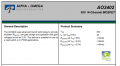
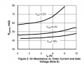
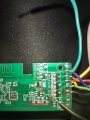
Hello everyone, recently i bought an rgb led strip and i tried to modify the controller to work with esp32. I desoldered everything from the premade controller except for the mosfets and the 2 resistors you see in the schematic. Mosftets are AO3402 (340s marking). After flashing the esp and connecting to gpio it blinks for few seconds and then it stays partially on. Shorting the gate to source doesn't turn it off. It's a 24v led strip and at first try i didnt have the grounds of powersupply - esp32 connected. I thought that was the problem but it happened on the second mosfet too. What could be wrong. On second try i also removed the 10k resistor.

Thanks in advance!

1ST.png 2ND.png
 

LesJones

Joined Jan 8, 2017
4,511
How much current does the LED strip take ? You do not show any current limiting resistors in your diagram. Are there current limiting resistors in the LED strip fo each series group of LEDs ?
Les.
 

Thread Starter

amachairas

Joined Mar 9, 2017
17
What is the part number for the LED strip? I assume it can work at 24V without a resistor.
What is the Gate to Source voltage?

Do you have the D and S reversed?
Generic chinese strip. Vgs is max 3.3v from esp32 gpio output.
I dont think i have it reversed because touching gate then shorting to source worked for the second mosfet before it burned.
Currently the 2 broken mosfets measure ~0.5v in diode mode D-S and S-D
 

KeithWalker

Joined Jul 10, 2017
3,603
What is the voltage on the gate of the FET when it is in the "on" condition? See the datasheet for the AO3402. At 3.3V gate to drain, the resistance of the FET will be around 50 ohms. What is the current through the LED strip? The FET is probably getting hot because it is dissipating so much power. Watts = I squared x R.
The best solutions will be to select a MOS FET with a logic level gate and much lower D/S resistance, or use a transistor to drive the gate with a much higher voltage.
 
Last edited:

Calmhand

Joined Dec 28, 2019
1
If you're unsure of the current draw from your LED strips, you may be exceeding the power dissipation limit of this MOSFET. With a gate-to-source voltage of only 3.3V, the MOSFET will not be fully on, leading to a higher Rds(on) and higher temperatures.

Consider using a high-side P-channel MOSFET load switch circuit. You could control the P-channel MOSFET with an N-channel MOSFET, which would manage the load from your LED strips more effectively.
 

ericgibbs

Joined Jan 29, 2010
21,390
hi ama,
That MOSFET wiring looks correct.
Do you have an ammeter that you could use to measure the LED current.?
Measure the current by first disconnecting the Drain wire to LED, then measure the current from that free wire to 0V. [ no MOSFET in the test circuit]
E
EG57_ 2237.png
 

Thread Starter

amachairas

Joined Mar 9, 2017
17
What is the voltage on the gate of the FET when it is in the "on" condition? See the datasheet for the AO3402. At 3.3V gate to drain, the resistance of the FET will be around 50 ohms. What is the current through the LED strip? The FET is probably getting hot because it is dissipating so much power. Watts = I squared x R.
The best solutions will be to select a MOS FET with a logic level gate and much lower D/S resistance, or use a transistor to drive the gate with a much higher voltage.
Facepalm time. Measured Vgs when on and its ~1.5V because i had the brightness set to 50% on the esp. What bothers me though is that i dont see a reason it would burn as the original controller could dim it 0-100%. When first testing it the mosfet was not even close to hot to the touch.
 

Thread Starter

amachairas

Joined Mar 9, 2017
17
hi ama,
That MOSFET wiring looks correct.
Do you have an ammeter that you could use to measure the LED current.?
Measure the current by first disconnecting the Drain wire to LED, then measure the current from that free wire to 0V. [ no MOSFET in the test circuit]
E
120ma for white and ~70ma for each color. However i'm using the power supply and the mosfets from the manufacturer. i dont think current draw could cause a problem in this case right?
 

ronsimpson

Joined Oct 7, 2019
4,646
Facepalm time. Measured Vgs when on and its ~1.5V because i had the brightness set to 50% on the esp. What bothers me though is that i dont see a reason it would burn as the original controller could dim it 0-100%. When first testing it the mosfet was not even close to hot to the touch.
?? How are you measuring Vgs. It sounds like with a meter.
Is this true. 3.0V at 100% and 1.5V at 50%. 0.7V at 25%.
 

panic mode

Joined Oct 10, 2011
4,864
are you sure that they are "burned"? how did you determine that heat was involved? if they got hot, certainly they could fail but
MOSFETs are also sensitive to static. touching gate can destroy them, it may have worked before but after removal of 10k resistor, gate is floating and increasingly sensitive.
 

Thread Starter

amachairas

Joined Mar 9, 2017
17
are you sure that they are "burned"? how did you determine that heat was involved? if they got hot, certainly they could fail but
MOSFETs are also sensitive to static. touching gate can destroy them, it may have worked before but after removal of 10k resistor, gate is floating and increasingly sensitive.
Well not burned per se but failed for sure. They were not hot to the touch so i dont think it was heat. I tried with and without the 10k resistor
 
Top