Facebook
 Google
 GitHub
 Linkedin
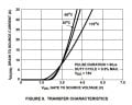
I have a PIR sensor that outputs 3.7v when active. it is powered by a 6v battery. I am trying to run flashing LED's (built in resistors) off 6v battery as well when the PIR sensor is high at 3.7v. is the IRF510 gate capable of being switched at 3.7v from the PIR sensor? also what else do I need to hook this up and how? The reason want the lights triggered with 6v rather than 3.7v is because they are too dim under 3.7v
Thanks in advance
Thanks in advance