Facebook
 Google
 GitHub
 Linkedin
Hi everyone! ") I am currently doing a project, which is on building a system to display Morse Code keyed into the system via a 4-bit DIP switch. The details are as follow:
I am currently doing a project, which is on building a system to display Morse Code keyed into the system via a 4-bit DIP switch. The details are as follow:

My attempt at the project:
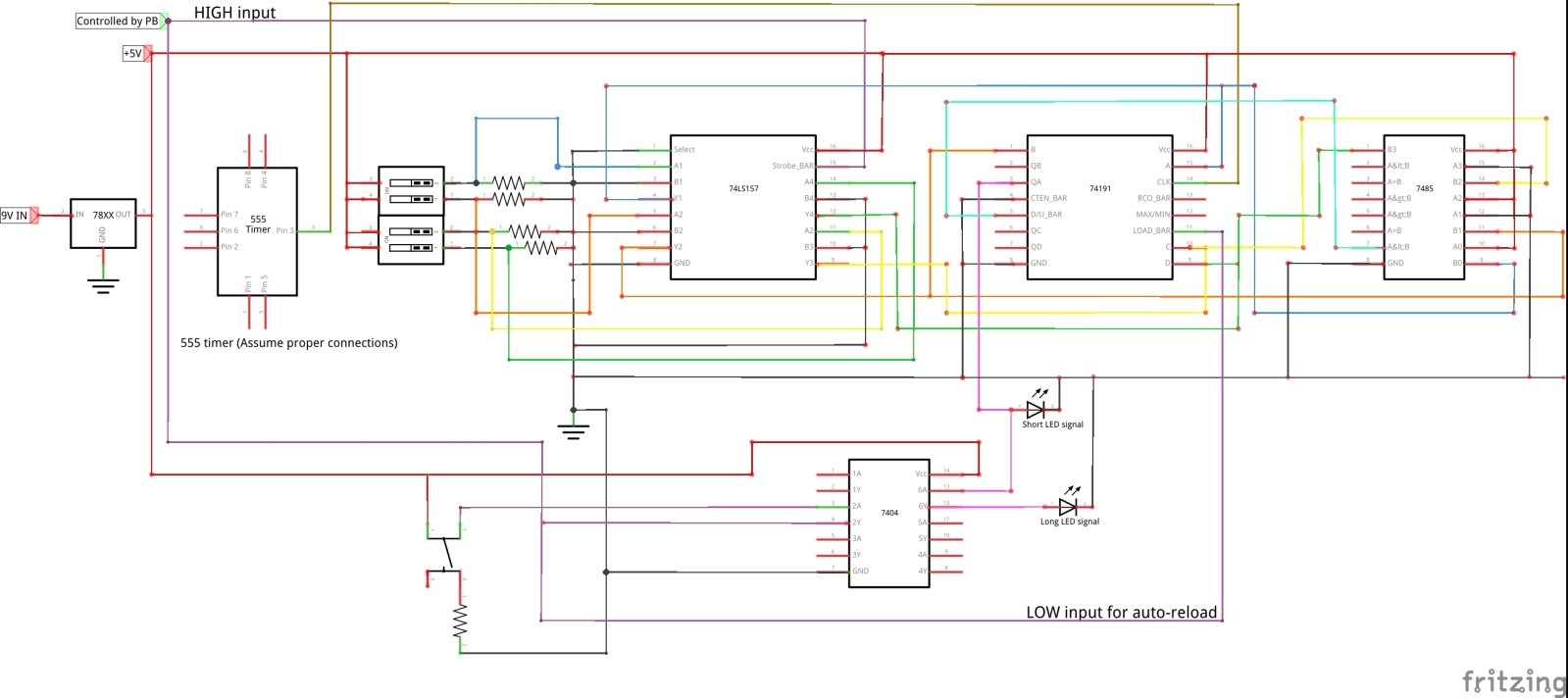
Currently, I have build up a system using several chips, listed below:
1. 555 timer
2. 4-bit DIP switch
3. 74157 MUX
4. 74191 Up/Down Counter
5. 7485 Comparator
6. 7404 NOT gate
I have built the system in such a way that it can read in a 4-bit binary digit from a 4-bit DIP switch, and output long and short signals from 2 LEDs, each representing short and long signals respectively. I noted that the order of display of long and short signals is complementary to one another, i.e. signals from 1 – 4 are the complement of 6—9.
A comparator is used, so that the chip 74191 counts down when the given number is less than 5, and it counts up when the given number is more than 5, via the D/U_BARport of 74191.
A NOT gate is put in, as the long and short signals of any given number, except for 5 and 0, are complements of one another.
Here is my breadboard of the circuit with some explanations:

The yellow LED in the middle is for the short signals, while the green LED is for long signal. The yellow LED at the extreme right of the photo is just an indicator of whether the PB is working correctly. PB stands for pushbutton. (Here I am assuming perfect conditions, so I neglected the circuit to debounce the circuit for simplicity). I have also labeled the chips for quick and easy identification.
My problem so far is that when I energized my circuit, none of my LEDs lit up, except for the LED indicating the output of the 555 timer. When I pushed my PB, the LED on the extreme right, which indicates whether the PB has completed the circuit lit up, but not my short and long LEDs. Interestingly, when I pushed and held the PB in place for an extended period of time, my short LED (yellow color LED exiting port 3 of 74191) lit up and flashed continuously without stopping, while my long LED (green color LED from NOT gate) did not light up once. I know I have done an illegal connection for my short LED due to a lack of space on my breadboard. Sorry. (But will it affect the circuit?)
Hence, may I have advice on how to solve the problems of my circuit? I took a look at my friends' projects and they all used almost 2 breadboards for the above project, but I only used one, which I think, may be a sign of trouble for me. Sigh.
I would appreciate any help/hints given as I am feeling a little stressed out over this project, which is due in 2-3 weeks' time. I have attached a document, documenting my thought processes in arriving at the above circuit. If there are any mistakes/loopholes in logic, please do feel free to correct me. Thank you very much.
**D1A, B and C are partitions of the big project. I am at the D1A to D1B stage at the moment.
Thank you once again.
I am currently doing a project, which is on building a system to display Morse Code keyed into the system via a 4-bit DIP switch. The details are as follow:
My attempt at the project:
Currently, I have build up a system using several chips, listed below:
1. 555 timer
2. 4-bit DIP switch
3. 74157 MUX
4. 74191 Up/Down Counter
5. 7485 Comparator
6. 7404 NOT gate
I have built the system in such a way that it can read in a 4-bit binary digit from a 4-bit DIP switch, and output long and short signals from 2 LEDs, each representing short and long signals respectively. I noted that the order of display of long and short signals is complementary to one another, i.e. signals from 1 – 4 are the complement of 6—9.
A comparator is used, so that the chip 74191 counts down when the given number is less than 5, and it counts up when the given number is more than 5, via the D/U_BARport of 74191.
A NOT gate is put in, as the long and short signals of any given number, except for 5 and 0, are complements of one another.
Here is my breadboard of the circuit with some explanations:
The yellow LED in the middle is for the short signals, while the green LED is for long signal. The yellow LED at the extreme right of the photo is just an indicator of whether the PB is working correctly. PB stands for pushbutton. (Here I am assuming perfect conditions, so I neglected the circuit to debounce the circuit for simplicity). I have also labeled the chips for quick and easy identification.
My problem so far is that when I energized my circuit, none of my LEDs lit up, except for the LED indicating the output of the 555 timer. When I pushed my PB, the LED on the extreme right, which indicates whether the PB has completed the circuit lit up, but not my short and long LEDs. Interestingly, when I pushed and held the PB in place for an extended period of time, my short LED (yellow color LED exiting port 3 of 74191) lit up and flashed continuously without stopping, while my long LED (green color LED from NOT gate) did not light up once. I know I have done an illegal connection for my short LED due to a lack of space on my breadboard. Sorry. (But will it affect the circuit?)
Hence, may I have advice on how to solve the problems of my circuit? I took a look at my friends' projects and they all used almost 2 breadboards for the above project, but I only used one, which I think, may be a sign of trouble for me. Sigh.
I would appreciate any help/hints given as I am feeling a little stressed out over this project, which is due in 2-3 weeks' time.
I have attached a document, documenting my thought processes in arriving at the above circuit. If there are any mistakes/loopholes in logic, please do feel free to correct me. Thank you very much. **D1A, B and C are partitions of the big project. I am at the D1A to D1B stage at the moment.
Thank you once again.
Attachments
-
559.3 KB Views: 92