Monitoring Series Batteries with Arduino ADC

crutschow

Joined Mar 14, 2008
38,669
From post #34
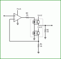
Maybe something like this.
You might consider using P-MOSFETs instead of BJTs to avoid the base-current (β) difference between the emitter and collector current, which typically will amount to an additional 1% or so error in the output voltage.
 
Iout*R3=V1 * R1/(R1+R2)
Vadc4=Iout*R14

If all resistors are 1% accurate, then the resulting voltage should be also 1% accurate. Unless the current you send is very small you should have no appreciable issues with offset voltage of the opamp.
Weird question is there anyway to adapt this circuit so the ADC voltages are optically isolated in some way? Can optocouplers be used in anyway i.e. when the voltage is converted to current can this current be used to drive an optooupler and in that way add some optical isolation or use of a photovoltaic driver?
 
Last edited:

kubeek

Joined Sep 20, 2005
5,796
Weird question is there anyway to adapt this circuit so the ADC voltages are optically isolated in some way? Can optocouplers be used in anyway i.e. when the voltage is converted to current can this current be used to drive an optooupler and in that way add some optical isolation or use of a photovoltaic driver?
Yes it can, but either the precision and temperature stability is not very good, or it costs quite a lot of money. Something like this configuration is typical https://i.stack.imgur.com/nXLwz.png or you can get dedicated isolation amplifiers.
 

MrAl

Joined Jun 17, 2014
13,761
Weird question is there anyway to adapt this circuit so the ADC voltages are optically isolated in some way? Can optocouplers be used in anyway i.e. when the voltage is converted to current can this current be used to drive an optooupler and in that way add some optical isolation or use of a photovoltaic driver?
There are opto couplers made just for analog signal but yes they are more expensive.
Normal opto couplers have to be used with caution as you cant go too high in the current or else the internal LED efficiency degrades over time and that degrades the current transfer ratio and that degrades the signal.

As you are finding out, a purely analog solution is not that simple.
It's not that hard to use four microcontrollers to monitor all four batteries, then using one as the host the other three send their readings to the host. The advantage here is you are directly measuring each battery with a separate ADC so there is no loss of resolution.

A really simple idea is to use four separate LED or LCD meters, then use a web cam to view all four on the PC.
 
There are opto couplers made just for analog signal but yes they are more expensive.
Normal opto couplers have to be used with caution as you cant go too high in the current or else the internal LED efficiency degrades over time and that degrades the current transfer ratio and that degrades the signal.

As you are finding out, a purely analog solution is not that simple.
It's not that hard to use four microcontrollers to monitor all four batteries, then using one as the host the other three send their readings to the host. The advantage here is you are directly measuring each battery with a separate ADC so there is no loss of resolution.

A really simple idea is to use four separate LED or LCD meters, then use a web cam to view all four on the PC.
Yep that's true I just wanted to see if there were any other analogue options thanks for the suggestion
 

k7elp60

Joined Nov 4, 2008
562
I had made an earlier post about opto couplers. The experiment that I talked about in my original post was made over 20 years ago. I did an experiment today with two sections of a PS2501-4 optocoupler. I used voltages from 12VDC TO 14.4VDC replicating 12V lead-acid batteries.
I went in steps of 0.4VDC I used a 22Kohm resistor in series with the input diode and the 12VDC power supply The input current to the opto coupler was 502uA I used a 560 ohm resistor between the collecter of the output transistor and a seperate 5VDC power supply, and the collector voltage of output transistor was 3.0VDC. As the input voltage to the diode of the opto coupler was increased by 0.4VDC the collector voltage was measured. As the diode current increased the output transistor voltage dropped. This is normal. The collector voltage could be inverted with an op amp and calibrated to the input voltage. The input voltages were 12.0,12.4,12.8,13.2,13.6,14.0,and 14.4VDC. the collector voltages were 3.0,2.9,2.8,2.6,2.5,2.4, and 2.2. so the 4th and 7th voltages were really not linear in my measurements. I then connected another of the 4 opto couplers in the package and took several readings. These reading were slightly different from the first set of readings.

So I guess it depends on the accuracy one needs when using opto couplers.
 

MrAl

Joined Jun 17, 2014
13,761
I had made an earlier post about opto couplers. The experiment that I talked about in my original post was made over 20 years ago. I did an experiment today with two sections of a PS2501-4 optocoupler. I used voltages from 12VDC TO 14.4VDC replicating 12V lead-acid batteries.
I went in steps of 0.4VDC I used a 22Kohm resistor in series with the input diode and the 12VDC power supply The input current to the opto coupler was 502uA I used a 560 ohm resistor between the collecter of the output transistor and a seperate 5VDC power supply, and the collector voltage of output transistor was 3.0VDC. As the input voltage to the diode of the opto coupler was increased by 0.4VDC the collector voltage was measured. As the diode current increased the output transistor voltage dropped. This is normal. The collector voltage could be inverted with an op amp and calibrated to the input voltage. The input voltages were 12.0,12.4,12.8,13.2,13.6,14.0,and 14.4VDC. the collector voltages were 3.0,2.9,2.8,2.6,2.5,2.4, and 2.2. so the 4th and 7th voltages were really not linear in my measurements. I then connected another of the 4 opto couplers in the package and took several readings. These reading were slightly different from the first set of readings.

So I guess it depends on the accuracy one needs when using opto couplers.
Hi,

Applause. I cant like a post any more than one where we see some real life test data. Thanks for taking the time to do this careful test.

Now if you care to, would you like to try another one?
If so, the idea is to use two optos in the same package, where one is used in the normal way and the other is used as feedback to adjust the first one. You can create an amplifier with gain of 1 with isolated output. If the two sections are similar, the output opto should follow the signal better because the second opto provides error feedback. An op amp is also needed.

You can probably find this circuit on the web if you want to try it, but if not i'll provide a circuit if you care to try it.
I wanted to do this for a long time but didnt get to it yet.
 

MrAl

Joined Jun 17, 2014
13,761
Mr Al, thank you for your positive comments. I will b happy to try a circuit. Please provide one for me.
Thanks, Ned
Hi again,

Here is a first version you can try. The optos should really be in the same package or use a dual-output-single-LED opto. R2 may have to be adjusted to get the right output voltage. With two identical opto's R2=R1 but they probably will not be identical. R3 value may go down a lot perhaps.

Note Vcc2 is the isolated voltage source from the isolated system typically +5v.
Also note the second ground (far right) can also be isolated (the ground in the second system that does not have to be common with the first system ground).

This arrangement of opto's allows for some change of CTR as long as the two opto's change about the same. A dual output single LED package works better for this though because the main source of CTR change is the LED aging.
There are actually linear isolated opto couplers made for this that track CTR over their expected lifetime; they are about $3 USD each. I dont have any on hand though.
 

Attachments

Last edited:

LesJones

Joined Jan 8, 2017
4,521
I have not been fully following this tread. Overnight I was thinking about it and was going to suggest what MrAl suggested in an earlier post. (I read it again from the start this morning.) I realised that a system that I use for remote monitoring could be adapted to this application. I use PIC12F1840 PICs together with HC-12 (Serial wireless link modules) I thought that using one PIC (Using it's internal ADC) for each 12 volt battery and then using optical isolators in palce of the wirleless link would solve the problem cheaply. (The software that I use in the PIC would work without modification.) But when I got near the end of the thread I saw RichardO's suggestion. I think that is the best solution so far.

Les.
 

MrAl

Joined Jun 17, 2014
13,761
Hello again,

I like the more complicated analog solutions too. The divider solution is the simplest though, and use a higher resolution ADC or oversampling.
The divider solution has a drawback in that the resolution suffers, but it just doesnt matter sometimes.

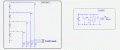
I included a drawing of the divider solution and also one section of the four uC solution. Interestingly, if we had a uC that can run up to maybe 16v we could do it with just four uC's and three standard opto's. Each of three sections would require 1 resistor to the opto,
The standard PIC 5v uC chips all require a small 5v regulator either surface mount or small 3 lead package. Raw accuracy then is whatever the ADC has.
 

Attachments

LesJones

Joined Jan 8, 2017
4,521
Hi MrAl,
Out of interest I just had a look at the price of the Op amps on RichardO's design. Each op amp is more expensive than the PIC12F1840 that I was thinking of using. The plan was to have 4 PICs (Each with a 5 volt regulator) and 4 dual optos (Or just 3 if the communication was referenced to the battery negative.) The plan was to output the data as a serial string from the USART. The 4 of these strings would be combined at the opto outputs to the host computer. The host would signal each PIC in turn which would respond with a reading. It could do this by pulsing a pin on the PIC via the opto or sending an address character from the host. (That was seen by all 4 PICs)
The sending an address method is the way I do it with each of my remote sensors which communicate via HC-12 RF link modules. The host computer sends a # character followed by a letter which is the address of the remote sensor to be selected. The PIC converts the ADC reading into a readable string of ASCII characters. (The # character must never be part of the return string sent by the PIC as all remote stations see all of the traffic on the HC-12 RF link) I have a Raspberry Pi with a program running that sends a request for data from a particular remote sensor, displays it on the screen and also writes it to a file than can be later be copied to a PC and converted to a graph using Excel. I can also request a reading directly from a PC running a terminal emulator program just by typing # followed by the address letter of the remote sensor.

Les.
 

MrAl

Joined Jun 17, 2014
13,761
Hi MrAl,
Out of interest I just had a look at the price of the Op amps on RichardO's design. Each op amp is more expensive than the PIC12F1840 that I was thinking of using. The plan was to have 4 PICs (Each with a 5 volt regulator) and 4 dual optos (Or just 3 if the communication was referenced to the battery negative.) The plan was to output the data as a serial string from the USART. The 4 of these strings would be combined at the opto outputs to the host computer. The host would signal each PIC in turn which would respond with a reading. It could do this by pulsing a pin on the PIC via the opto or sending an address character from the host. (That was seen by all 4 PICs)
The sending an address method is the way I do it with each of my remote sensors which communicate via HC-12 RF link modules. The host computer sends a # character followed by a letter which is the address of the remote sensor to be selected. The PIC converts the ADC reading into a readable string of ASCII characters. (The # character must never be part of the return string sent by the PIC as all remote stations see all of the traffic on the HC-12 RF link) I have a Raspberry Pi with a program running that sends a request for data from a particular remote sensor, displays it on the screen and also writes it to a file than can be later be copied to a PC and converted to a graph using Excel. I can also request a reading directly from a PC running a terminal emulator program just by typing # followed by the address letter of the remote sensor.

Les.

Hi again,

That sounds like a cool way to do it. The key point being that the data from each ADC unit is requested. That's a bit better than the way i would probably have ended up doing it, and that is just let the top three ADC's just keep sending data and when the host wants to read each of the three it just waits for the sync pulse and then accepts the data string. That's not quite as good as reqesting the data.
However just one question, what is the hardware means you want to use for this request? With only one opto for each of the top three ADC's there's no way to send data TOO the ADC of interest without having a two way comm setup. So i would be interested to hear how you intended to make this request in hardware, and if it can be done simply, that would be pretty good i think as then there would be no time wasted waiting for the sync pulse for each of the three top uC's.
 

LesJones

Joined Jan 8, 2017
4,521
First I did say dual optos (So there is two way communication to each PIC.)
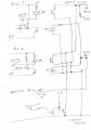
The static state of the serial data lines to and from the PIC is high so the photo diodes would be connected between +5V and the serial out pin from the PIC. On the host side the photo transistors would be all connected in parallel with the collectors to the host side +5V. The emitters would be connected via a resistor to the host ground and the emitters would be the data in to the host. This would form a sort of OR gate. As data has to be requested only one PIC could transmit data at any one time. For the data from the host to the PICs all of the photo diodes would be connected in parallel (With their own limiting resistors.) (Or they could be connected in series if a higher voltage rail than + 5V was available.) This is a very rough schematic of the idea.

040218.jpg
I have only shown 2 of the 3 upper PICs. The bottom part is how the link could be done to save one dual opto coupler. I think in practice it is not worth the cost saving for one dual opto. If the TS preferred to just pulse a pin on the PICs to request a reading the optos that I use to send an address could just send the pulse. I am assuming that the TS only needs a low sampling rate for monitoring batteties. When monitoring batteries on charge I only take a reading every minute.
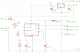
This is the schematic of the remote voltage monitor as I use it with an HC-12 module.

Monitor_V01.png
Although the schematic shows a PIC12F1822 I later changed to using PIC12F1840s
I also have a version that uses a DHT22 to monitor temperature and humidity and one using a INA219 to monitor voltage and current.

Les.
 
Top