Monitoring Series Batteries with Arduino ADC

Thread Starter

Jblack

Joined Feb 24, 2016
39
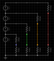
I need to measure the voltages of each cell in a battery pack made of four 12v SLA batteries connected in series with an Arduino. Obviously, I can't simply connect the batteries to the analog inputs of the Arduino, as the voltages are up to 48v nominal. I could use simple voltage dividers like the circuit below, but I would really like to avoid this if possible. The reason I don't want to use this is the accuracy differences; the first battery would have an accuracy of 12v/1024 = 12mv while the last battery would have an accuracy of 48v/1024 = 47mv. Another idea is to use a separate micro-controller (small like ATtin85) for each battery connected to the main Arduino via an isolated serial link. The problem with this is that I need to buy four additional micro-controllers and I would like to avoid that.
Any suggestions would be greatly appreciated.
Thanks
~Josh
 

Attachments

Reloadron

Joined Jan 15, 2015
7,893
Given the ways to go about doing this I would likely choose crutschow's suggestion. Using an Arduino you are limited to a single ended input on each channel. Using a high common mode difference amp will allow you to measure each 12 Volt battery's voltage individually. This will also afford a common ground which the Arduino analog inputs have. The typical 12 V SLA battery is about 12.6 to 12.7 volts when fully charged so I would use a high common mode difference amplifier as suggested along with a precision 3:1 divider (1% Resistors) on each Arduino input and do the scaling in your Arduino code. This way you know the voltage for each individual battery.

Ron
 

sghioto

Joined Dec 31, 2017
8,709
I could use simple voltage dividers like the circuit below, but I would really like to avoid this if possible. The reason I don't want to use this is the accuracy differences; the first battery would have an accuracy of 12v/1024 = 12mv while the last battery would have an accuracy of 48v/1024 = 47mv. I would like to avoid that.
~Josh
I'm not sure that logic is correct. A 10bit ADC with a 5 volt reference has a maximum resolution of just under 5mv regardless of which drop down resistor you are reading. The problem is when the batteries are all at different voltages which I'm sure is what you mean. I prefer the separate micro approach.
SG
 

crutschow

Joined Mar 14, 2008
38,596
I'm not sure that logic is correct. A 10bit ADC with a 5 volt reference has a maximum resolution of just under 5mv regardless of which drop down resistor you are reading.
He's referring to the resolution of the measured battery voltage, which does vary with the voltage divider value.
That would not occur if the difference amp is used.
 

Thread Starter

Jblack

Joined Feb 24, 2016
39
I was thinking of something similar to that, but I didn't know there were specific op-amps just for such a situation, I very much like that. The only thing I see is that these seem to require a dual supply (+-15v and gnd), I'm not entirely sure how I would go about connecting it up to the battery pack and Arduino. Would they still work if I put the low rail on gnd and the high rail on like 36v, instead of a dual supply? I can't tell just from the datasheet and I don't know enough about the theory of operation to figure it out.
Thanks
~Josh
 

Reloadron

Joined Jan 15, 2015
7,893
If you want to keep this simple, very simple, and can move away from using an Arduino there are dozens of inexpensive data acquisition systems out there available. Using this one as an example, Model DI-1100 from Dataq offers +/- 10 volt range with 4 differential channels. and starter kit packages like this include data acquisition software which allows charting and used annotation. The linked unit runs about $59 USD making it relatively inexpensive as a plug and play solution. The A/D is also 12 bit for relatively good resolution. Additionally most manufacturers pf data acquisition units like this also offer code samples in several languages for those who wish to roll their own code, however, the included software does a good job. Dataq offers a wide range of starter kits but just to monitor 4 batteries the DI-1100 I linked to is likely adequate for your purposes. All you would need is a 2:1 divider at the input which is easily done.

The small units like this are also powered off the USB again making for easy.

Ron
 
Last edited:

MrAl

Joined Jun 17, 2014
13,730
Hi,

I like the LT1990 idea, and you can even roll your own with a typical op amp as long as you pay attention to input offset errors.

Another solution if the application allows the slower speed of measurement is to use reed relays. This means the whole circuit has to be able to operate in a floating mode however, similar to how a multimeter works.

One thing you didnt mention is what has to power the arduino itself, a separate power source like a wall wart or the batteries under test.

Also, the resolution lost using voltage dividers may not be too bad, it depends how perfect you need to measure the voltage of the top or bottom battery. Let's think about this for a minute.
With 5v, the resolution is 5mv. With 10v, the resolution is 10mv, with 20v it is 20mv, so with 50v it is 50mv. That means the top battery has 10 times worse resolution, but is that bad? It all depends how exact you need this to be. Some applications would be fine with that, some not. Since this is just a monitoring application, it's probably ok.
Also, two batteries would be 24v and at full charge maybe 30v, so you could probably arrange this as a plus and minus 24v system rather than a 0v and 48v system and that would bring the resolution to around 30mv. That would bring the actual ADC resolution down to about 7.5 bits, which isnt that bad for a typical monitoring system unless you need high accuracy. You could also use oversampling to get better.

So there are a few choices, and whatever you think you need then becomes the best choice for this system.

The cost is also another point of view. Four MC PIC chips would cost about 4 dollars USD for example, but i dont know what your budget looks like either.


Thread Starter

Jblack

Joined Feb 24, 2016
39
If you want to keep this simple, very simple, and can move away from using an Arduino there are dozens of inexpensive data acquisition systems out there available. Using this one as an example, Model DI-1100 from Dataq offers +/- 10 volt range with 4 differential channels. and starter kit packages like this include data acquisition software which allows charting and used annotation. The linked unit runs about $59 USD making it relatively inexpensive as a plug and play solution. The A/D is also 12 bit for relatively good resolution. Additionally most manufacturers pf data acquisition units like this also offer code samples in several languages for those who wish to roll their own code, however, the included software does a good job. Dataq offers a wide range of starter kits but just to monitor 4 batteries the DI-1100 I linked to is likely adequate for your purposes. All you would need is a 2:1 divider at the input which is easily done.

The small units like this are also powered off the USB again making for easy.

Ron
I did consider that, but this is part of a battery monitoring system for a solar setup in Haiti, so I want it to be upgradeable and open source so that changes can be easily made after it's down there. The other reason is I want to make it as cheap as possible, and premade things tend to not be very cheap, as you said, the DI-1100 is on the cheaper end and is still $60.
 
Ron:
I just read the manual for the DI-1100 and it said that although “protected” differential inputs, they are not isolated and have a maximum CMRR of 10 volts. That tells me that it could not be used to simultaneously monitor all 4 series 12 V batteries in a 48 V string unless you divided them all down at least 5 to 1, which would mess up your resolution. I guess if you had multiple strings of 4 you could use 4 of the DI-1100s and tie each channel to the same cell in different strings relative to ground. Have you actually used this unit on a 48 Volt string? Maybe I am misreading the specs.
Dan
 
Ron:
I just read the manual for the DI-1100 and it said that although “protected” differential inputs, they are not isolated and have a maximum CMRR of 10 volts. That tells me that it could not be used to simultaneously monitor all 4 series 12 V batteries in a 48 V string unless you divided them all down at least 5 to 1, which would mess up your resolution. I guess if you had multiple strings of 4 you could use 4 of the DI-1100s and tie each channel to the same cell in different strings relative to ground. Have you actually used this unit on a 48 Volt string? Maybe I am misreading the specs.
Dan
I was pondering using opto isolated V to F converters, each one powered by the battery it is measuring, then counting their outputs with a digital in on the Arduino. Haven’t done it yet, but it seems like the easiest truly isolated option.
 

MrAl

Joined Jun 17, 2014
13,730
But each chip would need its power supply common referenced to the battery it was measuring, and the digital inputs and outputs would need optical isolation to the common ground.
Hi,

Yes to the first, not necessarily to the second.

Yes each chip needs to be running off of the battery it monitors. With micropower MC PIC chips that's not a problem and it might work down to 2.5v maybe lower. Since we have a 12v battery that can go say up to 15v, we get ADC resolution of about 15mv still so it does not help that unless we oversample. Each chip runs simultaneous with the others too so it's actually four ADC's not just one, which could be an advantage. I have a feeling speed is not that important however.
Note that micropower chips run from two AA cells for years so i would expect 12v LA to last longer especially since they are being charged regularly most likely.

For the second we might get by with capacitive coupling which eliminates the need for opto coupling, since the communication signal is AC.
Good observation on your part though :)
 

Reloadron

Joined Jan 15, 2015
7,893
Ron:
I just read the manual for the DI-1100 and it said that although “protected” differential inputs, they are not isolated and have a maximum CMRR of 10 volts. That tells me that it could not be used to simultaneously monitor all 4 series 12 V batteries in a 48 V string unless you divided them all down at least 5 to 1, which would mess up your resolution. I guess if you had multiple strings of 4 you could use 4 of the DI-1100s and tie each channel to the same cell in different strings relative to ground. Have you actually used this unit on a 48 Volt string? Maybe I am misreading the specs.
Dan
Dan, good catch there which I missed. I used earlier units now discontinued and I have used the DI 710. I have used them for monitoring battery strings but again the starter kits I used were older and out of production. DATAQ did provide really good SDKs making for easy program writing and I am far from a programming type. Thanks again for catching the CMRR issue as I read right through it.

That considered I would go back to Crutschow's proposal which I originally liked.

Ron
 

MrAl

Joined Jun 17, 2014
13,730
What communication signal is that?
Hi,

What do you mean? What would we use an opto for? We'd use it for communication to the Master. One of the four could be the master or a separate master depending on application needs. The master or host does the housekeeping while the others just have to read a voltage and send that data. Once the master gets all four (or three) data sets, it can display the results or something.

That's the way it would work with an opto coupler also, more or less.
I hope you didnt think i meant that we would be sending *analog*signals to the master.

LATER:
Back to the voltage divider, there is some benefit to using a negative bias supply to bias the voltage divider. It allows better resolution. For example, for a range of 40 to 60v input i can get a range of output of +5v down to about 0.7v with a -10v bias supply.
That beats a voltage divider to ground.
 
Last edited:
Top