Well the implication there is if you dont have one, then add one.
We could look at the details, but it looks like the benefits from using a negative supply, which BTW would not have to support too much current (10ma perhaps), would be pretty decent. Might get a little hairy though with all those resistors
I've done two battery setups before. That's with just two batteries in series, not four. The regular 0v voltage divider works pretty good unless we want to use the entire full ADC range to get highest resolution from a given ADC. There is also the possibility of going to a higher resolution ADC also, which would bring the effective bit count back up again to maybe 10 bits. There are ADC boards made more or less for Arduino that are 15 bit plus sign, so that would probably help a lot with the 0v voltage divider idea.
Top end would be i guess 60v, so that's about 60mv resolution with a 10bit ADC, so with 12 bits that's about 15mv, and with a 14 bit ADC that's about 4mv resolution. The boards are very cheap and have two differential input channels. That would mean two boards would be required.
Lots of possibilities here i guess.
Four ADC units (maybe with uC too) with RF transmitters would be wireless
The master would be the receiver.
A normal digital signal has a varying cycle of ones and zeros with sill cause a DC shift when AC coupled.
That needs to be considered when recovering the signal after the AC coupling.
A normal digital signal has a varying cycle of ones and zeros with sill cause a DC shift when AC coupled.
That needs to be considered when recovering the signal after the AC coupling.
Well, then DONT use a 'normal' digital signal then
One thing nice about designing a circuit ourselves is we get to choose such things. In particular for this circuit, we get to choose the comm protocol.
I think you might be referring to something like RS232, which probably wont work with capacitor coupling so any on chip peripheral that uses RS232 protocol probably can not be used unless maybe we modify the sending (and thus receiving) codes, and i think there is a way to do that although it's been many years for me on that issue. I would go with a custom protocol myself just because it's kind of fun to design such a thing, but there are ready made ones too that can be found on the web.
Actually though i dont think i would mind using opto couplers as i am sure they can be fast enough for a monitor program. I used opto's for RS232 direct to the RS232 port of the PC computer with multi channel ADC's and it's plenty fast enough to monitor battery voltages even with the cheap opto couplers.
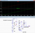
Here's the LTspice simulation of a differential amp using an inexpensive LM324 quad op amp to give a 3.3V-5V output for a 10V to 15V battery voltage.
But note that the output offset can be up to 500mV for 1% resistors and 50mV for 0.1% resistors when measuring the top battery voltage.
Dan, good catch there which I missed. I used earlier units now discontinued and I have used the DI 710. I have used them for monitoring battery strings but again the starter kits I used were older and out of production. DATAQ did provide really good SDKs making for easy program writing and I am far from a programming type. Thanks again for catching the CMRR issue as I read right through it.
That considered I would go back to Crutschow's proposal which I originally liked.
The issues I see with the diff amp idea is that the supply rails for the amp,must exceed the inputs, usually by 1/4 Volt or more. That means dc to dc converters for each isolated input channel. With a V to F converter or voltage dependent oscillator the power rails can be the input rails. I need to dig out a 331 and try it. Maybe tomorrow. And yes, it could be cap coupled instead of opto isolated. Typically the 331 series is set to run at 1 Hz / mV so at 12 volts it would be at 12 KHz, easily cap coupled and tracked by an Arduino
Here's the LTspice simulation of a differential amp using an inexpensive LM324 quad op amp to give a 3.3V-5V output for a 10V to 15V battery voltage.
But note that the output offset can be up to 500mV for 1% resistors and 50mV for 0.1% resistors when measuring the top battery voltage.
Is that with the model for the op amp that already includes input offset? I ask because that sounds kind of high.
Here's the output equation for an ideal op amp but with input offset voltage 'voff':
Vout=(-R1*R4*V2-R1*R3*V2+R2*R4*V1+R1*R4*V1+voff*R2*R4+voff*R1*R4+voff*R2*R3+voff*R1*R3)/(R2*(R4+R3))
where V1 is the 48v nominal top end and V2 is the bottom end (nominal 36v)
However, the top end can be as high as 60v with the bottom end as high as 45v, or even a little higher.
'voff' is the input offset applied to the non inverting input and can be either positive or negative.
To see the effect of mismatched resistors i set voff=0.
How about creating 4 floating current sources that reference the individual batteries to derive their output currents?
They could source current into resistors tied to ground, easy to measure the voltage across these with an ADC. At the very least, this could minimize common mode voltage issues.
How about creating 4 floating current sources that reference the individual batteries to derive their output currents?
They could source current into resistors tied to ground, easy to measure the voltage across these with an ADC. At the very least, this could minimize common mode voltage issues.
Well two of the issues are circuit complexity and accuracy. How complicated would that be relative to what has already been discussed.
Note that anything other than a direct measurement (floating ADC units) usually results in less accuracy. Sometimes it doesnt matter that much though.
So far i like the four ADC units (four uC chips) idea best because it measures each battery as an individual battery. Opto couplers are not that expensive either so the designer could even use the onboard RS232 interfaces perhaps.
Differential amp is very sensitive to mismatch of the resistors, and thus has very poor common mode rejection ratio, unless you manually balance the resistors.
A cheap and simple approach (if you can afford to waste a little bit of power from the batteries) is to have an opamp that does a voltage to current conversion at each battery, and sources this current towards ground. Then you sense this current at a resistor that is at ground and thus the potential of your arduino.
The output offset I'm referring to is due to resistor tolerance mismatch which determines the common-mode rejection, not from the op amp offset, which is much smaller.
Hello again, reply to last two posts in this thread...
I got 2.5 percent for a 1.0 percent change in one resistor value.
For all four in the most unfavorable directions that might total up to 10 percent, so yes there could be some issue if that's not good enough.
The resistors would have to be trimmed i guess.
That's not something we have to worry about when using four separate floating ADC's.
I think if you were to use 4 indiviual opto couplers or one IC that has 4 in a package that would work. I once did an experiment and discovered that opto couplers can be linear.
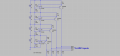
Maybe something like this. The op-amp might be an LM358 if you are not too worried about the constant load on the batteries. If a dual op-amp is used then one IC would be powered by the top 2 batteries and the other IC would be powered by the bottom 2 batteries.
The resistor values given are just a starting point.
Only your battery stack is upside down. Almost all 48 Volt systems are positive return (ground). I will give this a try, at first blush it looks reasonable.
Maybe something like this. The op-amp might be an LM358 if you are not too worried about the constant load on the batteries. If a dual op-amp is used then one IC would be powered by the top 2 batteries and the other IC would be powered by the bottom 2 batteries.
The resistor values given are just a starting point.
If all resistors are 1% accurate, then the resulting voltage should be also 1% accurate. Unless the current you send is very small you should have no appreciable issues with offset voltage of the opamp.

 Facebook
 Google
 GitHub
 Linkedin