 Facebook
 Google
 GitHub
 Linkedin
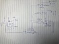
Hi everyone, I tried to design a modulo-2 to get this sequence 00,01,10,11,01,10,00. But glitch append at the ouput of the XNOR (cd4027) and trig the flipflop
randomly. So do you have any suggestions to design this circuit?
randomly. So do you have any suggestions to design this circuit?
Attachments
-
 2.2 MB Views: 32


