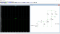
Hmmm. The base of Q6 is not the output. Is your truth table for the voltage applied to the base, or it is the required output. The output of your circuit is the collector of Q6 btw.
Hmmm. The base of Q6 is not the output. Is your truth table for the voltage applied to the base, or it is the required output. The output of your circuit is the collector of Q6 btw.
Q6 in you circuit will invert the voltage levels, so a second transistor is needed to invert the signal again to get the voltage levels you want. See below.
Q1 inverts, then Q2 inverts again so that 0v in=0v out, 5v in=12v out.
Hi,
The 91k resistor is correct, as the circuit continues with other parts that I didn't include because they are irrelevant to the trigger voltage being discussed..
Q6 in you circuit will invert the voltage levels, so a second transistor is needed to invert the signal again to get the voltage levels you want. See below.
Q1 inverts, then Q2 inverts again so that 0v in=0v out, 5v in=12v out.

 Facebook
 Google
 GitHub
 Linkedin