 Facebook
 Google
 GitHub
 Linkedin
Hello everyone,
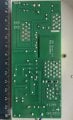
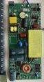
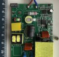
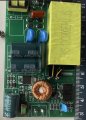
I have a constant current switching power supply (LED driver) that takes in 230V AC and provides a constant current output of 700mA. The output voltage is rated at 27V–43V (up to a maximum of 48V). I’d like to reduce the output current to around 400mA. Ideally, I’d love to make it adjustable, but even a fixed lower current would be fine.
Before I dive into any hardware modifications, I was hoping to get some advice from the community. Has anyone here successfully modified a similar driver to reduce its output current? If so, what approach did you take (e.g. swapping a feedback resistor, adjusting a potentiometer, etc.)? Are there any general rules or recommended practices for reducing the output current on these kinds of constant current supplies?
I’d appreciate any tips, warnings, or suggestions to help me do this safely and avoid damaging the driver. Thanks in advance for your expertise!
Attachments
-
 207.7 KB Views: 26
 -
 1.9 MB Views: 28
 -
 378 KB Views: 27
 -
 213.2 KB Views: 25
")


