 Facebook
 Google
 GitHub
 Linkedin
Hi,
Learning here.
Would need some help modifying this circuit.
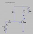
In the circuit below, V2 controls when Q6 conducts:
When V2 is set to a 5V (negative) voltage, you see 12V at Out.
When the output of V2 is changed to 0V, Out is close to 0V.
I would like to change it, so that it can be controlled by a voltage from a processor like an Arduino board:
5V turns Q6 on.
0V turns Q6 off.
Any ideas?

Learning here.
Would need some help modifying this circuit.
In the circuit below, V2 controls when Q6 conducts:
When V2 is set to a 5V (negative) voltage, you see 12V at Out.
When the output of V2 is changed to 0V, Out is close to 0V.
I would like to change it, so that it can be controlled by a voltage from a processor like an Arduino board:
5V turns Q6 on.
0V turns Q6 off.
Any ideas?
Attachments
-
 7.6 KB Views: 2


