Modifying Servo board for higher voltage/current NEED expert electronics advice!

Thread Starter

RCpaul

Joined Oct 26, 2012
16
Hello

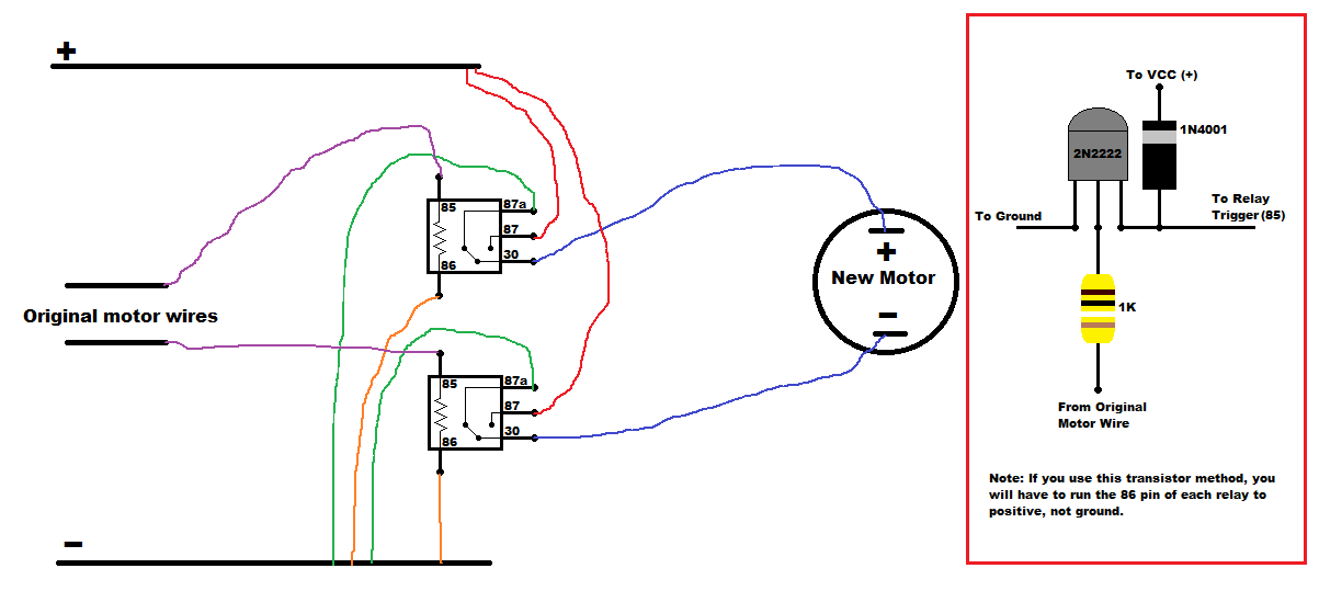
I am working on a project that requires me to add more voltage and current to my servos. I NEED to use the servos that I currently have but need to replace the servo motor with a larger more powerful servo motor. Does anyone know if I can take the two wires that are connected to the servo motor and connect them to some type of voltage/current regulator to power my larger servo motor?

Not sure if its a voltage regulator or current regulator that I need but I have already measured the voltage that comes from those two wires and its -6v-0-6v depending on the direction and speed of the servo. I would need to increase that voltage for my larger servo motor.

So if the signal voltage from those wires was -6 the regulator would supply -12v, if the signal voltage was 0v the regulator would provide 0v, and if the signal voltage was 6v the regulator would supply 12v and so on.

Any suggestions?

Thanks!
Paul
 

Sensacell

Joined Jun 19, 2012
3,432
Ok, you want to interpose a servo amplifier between the existing motor and a larger replacement motor?

This should work, with one caution; depending on what type of feedback system there is, i.e. if it's a closed loop system, the new driver and motor could upset the stability of the control system, causing oscillations, etc.

The change might give the system more / less 'gain' than it's designed / tuned for.
 

Thread Starter

RCpaul

Joined Oct 26, 2012
16
Ok I can test it, how would I go about building a servo amplifier?

I would like to provide the larger servo with 12-14v up to 10amps

Thanks!
Paul
 
How important is super fast reaction time? You could run 2 relays that are triggered off of the the 2 wires that went to the original motor...


Not sure what servo you are using, but if it didn't have enough current to drive the relay you could use a transistor between the original wires and the relay (I drew how to add that at the right). Obviously you would need to do a transistor for each relay/original motor wire. I think this would work as long as you chose the right relay.
 
Last edited:

Thread Starter

RCpaul

Joined Oct 26, 2012
16
NFA Fabrication,

Thanks for the reply. Reaction time is critical so if the transistor setup your talking about is faster than the relay I will try that. Also, I am not sure that the relay setup would work because I don't actually need just an "on/off" switch, if the original wires supply any voltage from 0v-6v the supply to the new motor would have to be the same plus 6v. So if the supply voltage from the original wires was .5v the new supply would have to be 6.5v or if the original voltage was 1v the new supply would have to be 7v and so on.
 

Thread Starter

RCpaul

Joined Oct 26, 2012
16
NFA Fabrication,

Was kinda in a rush this morning and didn't realize the transistor setup was actually to allow more current for the relay setup.

If reaction time is critical is there any other setup I could use?

I was looking into adding a motor driver between the 2 wires that went to the original motor and the new motor, would something like that work?

Thanks
Paul
 
NFA Fabrication,

I am going to try your relay setup, which relays would you recommend?

Thanks
Paul
I just tried a typically automotive relay on my adjustable power supply, and it would only consistently trigger at 6.5V and above (Figures). Thinking maybe something like this:

http://www.ebay.com/itm/Mini-5V-DC-...715?pt=LH_DefaultDomain_0&hash=item3379f0593b

But you may have to limit your servo input voltage to 5V instead of 6 to not overpower the relay coil (Although 6V may be just fine, not sure how sensitive they are), You could still run whatever voltage you want on your "New" motor.

What is your base servo, and what are you powering with the larger motor in the end?

Edit, this was listed in the description: Coil rated voltage: 3-48VDC. So you should be fine as long as you do not draw more than 10A.
 
Last edited:

Thread Starter

RCpaul

Joined Oct 26, 2012
16
NFA Fabrication,

Thanks for the reply. Will I not need two relays for each servo though? If the relay only triggers 3-48VDC, than my larger motor would only turn one direction with one relay right? I would have to add another relay to make it turn in the opposite direction right?

Edit, just found this thread
http://www.largescaleforums.com/showthread.php?t=6983
Will I need some diodes and filter capacitors if I run two relays? Mind helping with a diagram with the relay setup, diodes, and filter capacitors?
 
Last edited:

Thread Starter

RCpaul

Joined Oct 26, 2012
16
NFA Fabrication,

Received my relays but their a little different than the picture you drew, mind helping me connect them? Thanks!

 
Top