Modifying K8064 to run 95W motor.

Thread Starter

vane

Joined Feb 28, 2007
189
Hi guys/possibly ladies,
I am making a cnc controlled motor speed controller for a 95W 240v motor (DC rectified). I took a chance and bought the velleman K8064 optically isolated triac lighting dimmer circuit hoping it would be able to run a motor and be a plug and play option but alas it is not completely. The device is rated to 750W at 240v which is much higher than the motor power.

The original controller for the motor had a 2 speed triac based speed selector which I removed in favour of a home made closed loop speed control so I know triac control of this motor is possible.

My problem is that the board's internal diagnostic flashes "Phase shift too great" and stops output when the motor is run over about half.

Can any of you much smarter than me guys/gals suggest any modifications to this circuit that will allow it to run a motor?

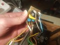
Circuit diagram is attached.
Thanks in advance!
Pete
 

Attachments

MaxHeadRoom

Joined Jul 18, 2013
28,576
For CNC control PWM is definitely better than Triac/phase angle control.
There are the KB versions, also something like the ex Treadmill MC2100 for very smooth and quiet control down to low RPM.
This is the reason Triac control is never used for CNC servo operation.
Max.
 

Thread Starter

vane

Joined Feb 28, 2007
189
I don't know if you misunderstood what I was doing, this is spindle speed not cnc axis servo control.

As it stands the motor has a magnet switch (may have to be inhibited for it to start correctly I know) and rectifier built in (used to have the triac as well) then a mains plug. If possible I would like to make my system bridge between the mains plug and the wall socket, so the motor can be used with and without it.

Using the device you mentioned I assume I will need to do the rectification earlier on than is happening now?
 
Last edited:

MaxHeadRoom

Joined Jul 18, 2013
28,576
I am assuming this is a DC PM field motor, not Universal type?
My preference for a spindle, especially if going down to low RPM's would still be PWM.
Show or post details of the motor.
The controllers I mentioned, have built in supply.
Max.
 

Thread Starter

vane

Joined Feb 28, 2007
189
Yes, DC permanent magnet running on 240v DC rectified from wall AC. The motor is a unimat 4 micro lathe motor.

Is there anything stopping me from rectifying then just using MOSFETs to control the 240v, with an opto isolator to control it from an arduino?

My original question was around making my hardware work but if you believe going this way is better than modding the AC waveform it's probably best to give the bigger picture. My main goal with the project is to make a speed controller that takes the spindle speed pwm signal (no closed loop control) from a GRBL stepper driver board and run it through the the arduino which alters motor power to attain the correct RPM based on a hal effect sensor mounted on the spindle output shaft, with provisions for custom features like program halt if the requested RPM cannot be attained due to belt drive limitations. The arduino software and hardware I can do, just the motor controlling i am having the problem with.
 

Attachments

MaxHeadRoom

Joined Jul 18, 2013
28,576
If going the Mosfet route, PWM should be possible with Arduino, I do it with a PICmicro so it should be just as easy also with Arduino.
Just that you will need a 240vDC supply if not already in place.
You would need a H-Bridge Mosfet set up if needing reverse motor operation.
Max.
 

Thread Starter

vane

Joined Feb 28, 2007
189
Well I would probably reuse the rectifier currently in the control module for the 240v DC. I've realised it is a bit silly to try and make a seperate module, I will probably just build it into a box on the motor, hoping it does not make it too much more bulky.

95 Watts at 240v is about 400mA so I shouldn't need that big of a mosfet but reversability sounds like a very useful function. Are there special H bridge MOSFETs so there is no chance of accidentally shorting the supply?

Cheers,
Pete

EDIT: So I kind of answered my own question, they are available. So I am after a high voltage capable full H bridge and say 2 amps max current for future proofing would be a good idea. Are there any reputable ones which are commonly used?
 
Last edited:

MaxHeadRoom

Joined Jul 18, 2013
28,576
I don't know of any for that voltage that are already in modular form.
There are quite a few circuits designs out there for Mosfet bridge such as this.
Max.
 

MaxHeadRoom

Joined Jul 18, 2013
28,576
There is however quite a few servo drives that will drive this motor and can often be found on ebay for fairly reasonable price.
The popular ones are A-M-C, Copley Controls, Aerotech etc, these use a ±10vdc signal for bi-directional control.
Also KB make PWM DC drives.
Max.
 
Top