 Facebook
 Google
 GitHub
 Linkedin
i am trying to modify this dishwahser pump, so the triac to work with phase shift (if is correct the terminology) am posting the pictures so you may understand better and explain to me olso, how i will make this pump, to spin.


this pump has this circuit old fashion board, that is driving the gate for a t410-610t triac, but the printed board get damage, some lines have been cut off, any way i try to solder the lines and e.tc but it was useless, i try to found some information in internet about this ic, EM2030 90C909 BUT NOTHING IN GOOGLE. so i make the thought to make the triac to work around with out this board.

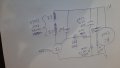
i read a lot about the triac and watch many tutorials but it seams something i do wrong.. what i did is in the picture below.

i have try many ressistor values, for charching the capacitor, i try deferent capacitors.. start from 470ohm up to 220kohm and capacitors from 7nf up to 2.2μf , some times the motor spins for a few rounds but most of time is stand still, and the coils get hot. what i notice with my osciloscope, is that in gate of the triac, i done have the small trigering pulse, (discharching capacitor) but i have a AC wave form, slightly ofset few degress.

the rotor of this pump is a magnet like you can see in the picture above.. my idea how this pump work is, that in the positive cycle the magnets are north/south and in the negative pulse the reverse south/north, if i am correct, i assume the controller of the triac that has been damage, is driving the gate of the triac, in half phase positive gate current, and in the other half negative gate current. so in the first half the current inside the triac flows from mt1 to mt2 and in the other half the current is flows from mt2 to mt2. with a result the coils to have a polarity change, so and there magnetic fields.
UNFORTUNATLY, SOMETHING SERIOUS I AM MISSING, AND THE MOTOR IS NOT SPINNING. CAN YOU HELP ME PLEASE.

this pump has this circuit old fashion board, that is driving the gate for a t410-610t triac, but the printed board get damage, some lines have been cut off, any way i try to solder the lines and e.tc but it was useless, i try to found some information in internet about this ic, EM2030 90C909 BUT NOTHING IN GOOGLE. so i make the thought to make the triac to work around with out this board.
i read a lot about the triac and watch many tutorials but it seams something i do wrong.. what i did is in the picture below.
i have try many ressistor values, for charching the capacitor, i try deferent capacitors.. start from 470ohm up to 220kohm and capacitors from 7nf up to 2.2μf , some times the motor spins for a few rounds but most of time is stand still, and the coils get hot. what i notice with my osciloscope, is that in gate of the triac, i done have the small trigering pulse, (discharching capacitor) but i have a AC wave form, slightly ofset few degress.
the rotor of this pump is a magnet like you can see in the picture above.. my idea how this pump work is, that in the positive cycle the magnets are north/south and in the negative pulse the reverse south/north, if i am correct, i assume the controller of the triac that has been damage, is driving the gate of the triac, in half phase positive gate current, and in the other half negative gate current. so in the first half the current inside the triac flows from mt1 to mt2 and in the other half the current is flows from mt2 to mt2. with a result the coils to have a polarity change, so and there magnetic fields.
UNFORTUNATLY, SOMETHING SERIOUS I AM MISSING, AND THE MOTOR IS NOT SPINNING. CAN YOU HELP ME PLEASE.
Attachments
-
 103 KB Views: 0


