Microphone circuit chart

Thread Starter

riversun

Joined Oct 31, 2024
32
Hello,

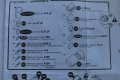
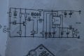
Is there anybody who could tell me how this circuit should be changed in order for it to work for recording? I mean replacing the speaker (LS) to mono TRS jack for output signal. It is parabolic microphone and as such works quite good.
 

Attachments

seanstevens

Joined Sep 22, 2009
323
I would use a voltage divider with a couple of resistors to reduce the output level to a level suitable for a recording device's line-in or mic-in. A resistor from C3, junction LS, to another resistor going to ground/negative (that's 2 resistors in series) Then the junction of the two resistors would be your output for recording. You can dimension the resistors for the recording device you have.
 

Thread Starter

riversun

Joined Oct 31, 2024
32
Thank you for your advice! I have the mixpre 3 ii recorder that has these kind of input:
  • Mic: XLR active-balanced; 4k input
  • Line: XLR active-balanced; 4k input...........how should one dimension the resistors for this?
 

MisterBill2

Joined Jan 23, 2018
27,177
With a balanced XLR input for both line input and microphone inputs it gets complicated. Does your recorder instruction book include any information about using unbalanced inputs??
The signal at P1 wiper might be suitable as is.
Actually, the signal between the wiper of P1 and the bottom of P1 would be a good start. Be sure to also connect the shield to the circuit common side, which is the bottom of P1.

And a question about that amplifier: what type number is the IC??
 

sghioto

Joined Dec 31, 2017
8,633
Thank you for your advice! I have the mixpre 3 ii recorder that has these kind of input:
  • Mic: XLR active-balanced; 4k input
  • Line: XLR active-balanced; 4k input...........how should one dimension the resistors for this?
Shouldn't need that circuit the recorder has preamps.
Does this parabolic use a lavalier type mic?
 
Last edited:

Thread Starter

riversun

Joined Oct 31, 2024
32
With a balanced XLR input for both line input and microphone inputs it gets complicated. Does your recorder instruction book include any information about using unbalanced inputs??

Actually, the signal between the wiper of P1 and the bottom of P1 would be a good start. Be sure to also connect the shield to the circuit common side, which is the bottom of P1.

And a question about that amplifier: what type number is the IC??
the ic is U2822B
 

Thread Starter

riversun

Joined Oct 31, 2024
32
With a balanced XLR input for both line input and microphone inputs it gets complicated. Does your recorder instruction book include any information about using unbalanced inputs??

Actually, the signal between the wiper of P1 and the bottom of P1 would be a good start. Be sure to also connect the shield to the circuit common side, which is the bottom of P1.

And a question about that amplifier: what type number is the IC??
I have been recording with self-made amplifier and pietzo contact mic using a DI box 'The primary function of DI boxes is to take an unbalanced, high-impedance signal and convert it to a balanced, low-impedance signal.' Would it solve the problem if I just connect between the circuit and the recorder this DI box or do I still need to add the resistors to this circuit?
 

MisterBill2

Joined Jan 23, 2018
27,177
Probably the DI box will work very well. I would have suggested that initially, except that a DI box costs a lot more than the connection addition that I suggested. AND the DI box avoids the requirement of getting the balanced input connection right.

AND, in response to "sg", the parts list for the amplifier shows an electret microphone cartridge, which always requires a "bias" voltage for the internal FET transistor.
 

Thread Starter

riversun

Joined Oct 31, 2024
32
so it is ok to just change a TRS cable in place of the LS speaker and no resistor added when DI box used? I appriciate anyway the information about the resistors for learning as it took me a very long time to get this circuit working!
 

MisterBill2

Joined Jan 23, 2018
27,177
so it is ok to just change a TRS cable in place of the LS speaker and no resistor added when DI box used? I appriciate anyway the information about the resistors for learning as it took me a very long time to get this circuit working!
That would depend very much on the input signal level that the DI box is intended to handle. Direct Input "boxes" include a wide variety of arrangements because of the variety of devices they may connect to. Adapting a Juke Box output to a PA balanced mic input is much different from adapting an electric guitar output to a mic balanced input.
And the connection suggested in posts #4 and #5 may also work if your DI box is only for low level signals like an unbalanced crystal microphone or an electric guitar magnetic pickup.
 

MisterBill2

Joined Jan 23, 2018
27,177
The DI box may provide DC blocking on the output, if you are at all lucky. If you are able to open it and look, or open it and post an in-focus picture, somebody here can help. OR, iif you have a voltmeter you can connect the DI box to the recorder and check for voltage at the INPUT to the DI box.
OR, you can add a capacitor in series with the TRS connector you add to your parabolic microphone system. Then you know you will be safe. BUT it is more work.
 

MisterBill2

Joined Jan 23, 2018
27,177
An actual "condenser" microphone would PROBABLY NOT be a Parabolic Reflector type, which is the mic of choice for the unknown application. I try to avoid telling folks what to do when I am not at all familiar with what they are trying to achieve. AND, This TS was quite clear as to enough details in post #1, so it was not that we had to ask a lot of questions.
 

AnalogKid

Joined Aug 1, 2013
12,043
the ic is U2822B
In case no one has said this yet, that is a very poor IC to use as a mic preamp. It is around 5x noisier than a decent preamp chip and 10x noisier than a high-end IC. Also, it has relatively high harmonic and crossover distortion, and low gain and bandwidth. As a small speaker amp for a portable radio or audio cassette player it was fine, but not for "real" audio.

And then there is the T1 circuit . . .

ak
 

MisterBill2

Joined Jan 23, 2018
27,177
In case no one has said this yet, that is a very poor IC to use as a mic preamp. It is around 5x noisier than a decent preamp chip and 10x noisier than a high-end IC. Also, it has relatively high harmonic and crossover distortion, and low gain and bandwidth. As a small speaker amp for a portable radio or audio cassette player it was fine, but not for "real" audio.

And then there is the T1 circuit . . .

ak
A.K is correct! THAT is the reason that I suggested tapping in before the amplifier IC.
 
Top