 Facebook
 Google
 GitHub
 Linkedin
Hello guys! I'm trying to build a small circuit that can detect a faulty microphone or an intermittent microphone. It is meant to be used with lavalier microphone.
So I asked chat GPT for ideas (yes aha) and it came up with this. Does it make any sense? I tried to put it quickly on a breadboard but it doesn't seem to work at all...
Have better ideas?
Thanks!!
Description:
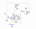
This circuit uses an LM358 dual operational amplifier to create an oscillator that produces an audio tone. The microphone's signal is compared to this tone, and if the microphone is functioning correctly, a green LED lights up. If a fault is detected, such as cable intermittence or a non-working microphone, a red LED lights up.
Parts List:
So I asked chat GPT for ideas (yes aha) and it came up with this. Does it make any sense? I tried to put it quickly on a breadboard but it doesn't seem to work at all...
Have better ideas?
Thanks!!
Description:
This circuit uses an LM358 dual operational amplifier to create an oscillator that produces an audio tone. The microphone's signal is compared to this tone, and if the microphone is functioning correctly, a green LED lights up. If a fault is detected, such as cable intermittence or a non-working microphone, a red LED lights up.
Parts List:
- LM358 Dual Operational Amplifier
- 2N3904 NPN Transistor
- Green LED (Pass Indicator)
- Red LED (Fail Indicator)
- Resistors:
- R1: 1k Ohm
- R2: 10k Ohm
- R3: 10k Ohm
- R4: 1k Ohm (for Green LED)
- R5: 1k Ohm (for Red LED)
- Capacitor:
- C1: 1uF
- On/Off Switch (SW1)
- Microphone (3.5mm)
- 3V Rechargeable Battery
- Breadboard or PCB for prototyping
- Jumper wires
- Power Section:
- Toggle the On/Off switch (SW1) to power the circuit with a 3V rechargeable battery.
- Oscillator Section:
- The LM358 generates an audio tone oscillator with resistors R1, R2, R3, and capacitor C1.
- The tone is compared with the microphone's signal.
- Microphone Section:
- The microphone is connected to the circuit.
- The microphone's signal is fed into the LM358.
- Indicator LEDs Section:
- If the microphone is working, the green LED lights up.
- If a fault is detected (such as no signal or intermittence), the red LED lights up.
- Turn on the circuit using the On/Off switch.
- Plug the lavalier microphone into the 3.5mm jack.
- The green LED lights up if the microphone is functioning properly.
- The red LED lights up if a fault is detected (cable intermittence or non-working microphone).
- Toggle the On/Off switch to power off the circuit when testing is complete.
- The circuit does not require external sound input.
- The green LED indicates a functioning microphone, while the red LED indicates a fault.
- Customize resistor values as needed for specific LED brightness.
- Build the circuit on a breadboard or PCB for testing and troubleshooting.
Attachments
-
 121.6 KB Views: 28


