Electret Microphone to TI ADC Interface Circuit

Thread Starter

Airspeed76

Joined Jun 4, 2020
12
Dear friends,

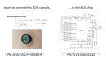
I would like to interface four electret microphones to a Texas Instruments TLV320ADC6140 ADC chip. My question is, what is the best way to go about this for optimal performance?

Should I use a pre-amp circuit, or can I bias the MIC and connect directly to the ADC via AC coupling capacitors?

Additional context:

[1] All four microphones will be mounted to the same PCB as the ADC

[2] low noise / high SNR is a key factor... Achieving low phase distortion is even more important.

[3] I would also like to minimise size and cost, so component count is a consideration

[4] Required bandwidth - 50 Hz to circa. 16 kHz.

[5] I don't want to use an OpAmp because of point [2]

[6] I don't want to use MEMs as the SNR is inferior to electret currently.

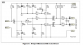
In summary, should I use a transistor preamp circuit, as shown in the attachments, or can I connect directly to the ADC?
Note that the ADC datasheet example shows MEMs microphones connected without preamps. These are presumably low output impedance.
What do you reckon experts?

Thx!
 

Attachments

LowQCab

Joined Nov 6, 2012
5,101
What is the purpose of this Project ?, Please give as much detail as practical.

You will have plenty of Phase-Distortion because of the multiple Mics,
this can't be avoided with your proposed approach.

There are plenty of extremely quiet Op-Amps available, with much lower overall Distortion.
.
.
.
 

Ian0

Joined Aug 7, 2020
13,114
That’s a good mic, but at 80dB SNR it still can only manage the equivalent of 13.5 bits, so an expensive ADC is wasted on it.
If component count is important, connect it straight to the ADC and trade resolution for gain. If price is important a bog-standard 16-bit audio ADC would do the job, but you would need some gain, and any cheap audio amp especially the venerable NE5532 would give you that without compromising the SNR.
How loud are the sounds you want to measure? How quiet is your power supply?
 

Thread Starter

Airspeed76

Joined Jun 4, 2020
12
That’s a good mic, but at 80dB SNR it still can only manage the equivalent of 13.5 bits, so an expensive ADC is wasted on it.
If component count is important, connect it straight to the ADC and trade resolution for gain. If price is important a bog-standard 16-bit audio ADC would do the job, but you would need some gain, and any cheap audio amp especially the venerable NE5532 would give you that without compromising the SNR.
How loud are the sounds you want to measure? How quiet is your power supply?
Its a good point. Its is a very good ADC. I don't need gain in the amp, as there is a programable gain block inside the ADC.
 

Thread Starter

Airspeed76

Joined Jun 4, 2020
12
What is the purpose of this Project ?, Please give as much detail as practical.

You will have plenty of Phase-Distortion because of the multiple Mics,
this can't be avoided with your proposed approach.

There are plenty of extremely quiet Op-Amps available, with much lower overall Distortion.
.
.
.
I'm using it for a phased array. I want to accurately measure phase differences between the mics, so I need a similar phase response across channels.
 

Thread Starter

Airspeed76

Joined Jun 4, 2020
12
So, I think where I am with this is that I most likely need a buffer to present a low impedance output from the microphone, because the input impedance of the ADC is not actually that high (2.5, 10 or 20 kOhm), and the output impedance of the microphone is a couple of kOhm. I don't necessarily need it to add any additional signal gain, due to the internal PGA inside the ADC. My question remains in that I am stuck between a discrete transistor pre-amplifier design and an OpAmp. After doing a bit of digging, I believe that most high end microphone preamps use discrete circuits because they are required to run on very low currents due to limitations in the phantom power supplies. I don't have this limitation as I can design a power supply to run OpAmps if needed.
 

Ian0

Joined Aug 7, 2020
13,114
So, I think where I am with this is that I most likely need a buffer to present a low impedance output from the microphone, because the input impedance of the ADC is not actually that high (2.5, 10 or 20 kOhm), and the output impedance of the microphone is a couple of kOhm. I don't necessarily need it to add any additional signal gain, due to the internal PGA inside the ADC. My question remains in that I am stuck between a discrete transistor pre-amplifier design and an OpAmp. After doing a bit of digging, I believe that most high end microphone preamps use discrete circuits because they are required to run on very low currents due to limitations in the phantom power supplies. I don't have this limitation as I can design a power supply to run OpAmps if needed.
The output impedance of the microphone is equal to its bias resistor, specified at 2.5k (as if 2.5k is a common value), so 20k input resistance should be no problem.
 

Thread Starter

Airspeed76

Joined Jun 4, 2020
12
Connecting Electret Microphones to TLV320ADC6140 – Preamp or Direct Connection?

Greetings all,

I'm currently working to connect four electret microphones to the TLV320ADC6140 and would appreciate any expert advice concerning the concerns of performance, specifically phase distortion, and noise.

My Primary Needs Are:

Every microphone integrated into one PCB with the ADC.

Lowest noise floor and High SNR.

Critical to the design is the requirement for minimal phase distortion.

The operating range is from 50 Hz to ~16 kHz.

Total size, cost, and the number of components needs to be minimized.

The use of OpAms should be avoided due to the aforementioned concerns relating to distortion and phase shift.

They should not be MEMS microphones because my tests show their SNR is much weaker than electret microphones.

The Principal Inquiry Is:

Am I able to connect electret microphones directly to the TLV320ADC6140 via AC coupling capacitors and bias resistors, or use a transistor preamp circuit?

The reason the TLV320ADC6140 shows MEMS mics connected directly is probably their low output impedance and also because they have integrated amplifiers. With electret microphones, it is usually several millivolts due to their high output impedance. So my questions are:

Is the input impedance sufficient and does the internal biasing scheme permit direct connection using only biasing and AC coupling?

Or is it still possible to require a discrete low noise preamplifier to bring the signal into optimal range for the ADC?

Are there applicable trade-offs in phase linearity with a simple BJT preamp which need to be kept in mind?

What I'm Looking For:

Use-cases or authoritative literature explaining the interfacing of electret microphones with audio ADCs, especially the TLV320.

Any thoughts on if a minimalist preamp adds anything (like phase accuracy) or is better omitted, say JFET or BJT common-emitter?

Thank you for your thoughts!
Thanks. You are kind of repeating my question though.
 

AnalogKid

Joined Aug 1, 2013
12,088
The output impedance of the microphone is equal to its bias resistor, specified at 2.5k (as if 2.5k is a common value), so 20k input resistance should be no problem.
That's over 1 dB of amplitude error. Also, we don't know the tolerance of either of those impedances, so there could be a significant channel-to-channel difference in attenuation. Depending on which part(s) of the waveform are being analyzed to extract phase information, that could be a problem.

ak
 
Last edited:

LowQCab

Joined Nov 6, 2012
5,101
If there is an inter-channel phase error, that will yield an error in the spatial domain.
.
Why can't You simply state what your project is supposed to do ?
Its starting to sound like You don't really know yourself,
but I guess the important sounding phrases make it all totally "official".

I've been known to be somewhat dense on occasion,
but I can't think of a single practical use for such an arrangement of Microphones,
especially when also requiring "ultra-quiet" Amplifiers,
and over such a wide Frequency-range of ~50Hz to ~16kHz.
( If it operated at a fixed-Frequency it might start to make "some" sense )

Please enlighten me and entertain my foolishness, even if it's only a link.
.
.
.
 

Thread Starter

Airspeed76

Joined Jun 4, 2020
12
That's over 1 dB of amplitude error. Also, we don't know the tolerance of either of those impedances, so there could be a significant channel-to-channel difference in attenuation. Depending on which part(s) of the waveform are being analyzed to extract phase information, that could be a problem.

ak
I can select the 2k2 bias resistor for the microphones. I will most likely use 1% metal film for this. But you are right, the tolerance around the impedance of the ADC is not published in the datasheet. This is most likely not a problem though. - I'm using a GCC-PHAT algorithm for direction finding, which, as I understand it, discards amplitude and uses the phase information from an FFT.

I'm leaning towards a direct connection between the two circuits.

Thanks to you and Ian0 for your constructive and civil contributions.
 

Ian0

Joined Aug 7, 2020
13,114
I can select the 2k2 bias resistor for the microphones. I will most likely use 1% metal film for this. But you are right, the tolerance around the impedance of the ADC is not published in the datasheet. This is most likely not a problem though. - I'm using a GCC-PHAT algorithm for direction finding, which, as I understand it, discards amplitude and uses the phase information from an FFT.

I'm leaning towards a direct connection between the two circuits.

Thanks to you and Ian0 for your constructive and civil contributions.
As @AnalogKid and @BobTPH mention, check on the datasheet how closely matched the input resistances are for the various channels. As your 2.2k bias resistor dominates the load on the microphone, a mismatch of ±10% on the device will only account to a mismatch of the load of around 1%, which is a similar order of magnitude as the tolerance in your load resistor.
 
Top