Microcontroller Based DC Converter

Thread Starter

sidd342

Joined Oct 9, 2023
26
Hey,

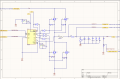
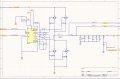
I'm trying an ambitious project, making a DC converter using a microcontroller.
I'm using a PNP transistor to drive both the high side and the low side MOSFET. When I'm trying the circuit, even if I keep the duty cycle as low as 20%, there is a path to the ground for the current (I'm able to observe this because my power supply goes to constant current mode from constant voltage mode)

I'm using the inbuilt PWM capability of the controller with complementary outputs and a dead time.
Please find attached my schematic and help me figure out the issue.

Thanks
Siddharth
 

Attachments

schmitt trigger

Joined Jul 12, 2010
966
The full bridge Mosfet drive is completely wrong and must be discarded.

Search the web for full bridge drivers, there are many ICs that perform that function, which you will see it is far more complex than your simplistic circuit.
 

Alec_t

Joined Sep 17, 2013
14,425
1) With no gate-to-source pull-down resistors, and no active pull-down until the micro boots up and configures its ports correctly, there is likely a period when significant shoot-through current occurs with both high and low side MOSFETs conducting at the same time. Hence your power supply behaviour.
2) The high-side MOSFETs can't turn on fully to pull the source high unless the gate goes several volts above the positive rail. Gate-drive ICs (e.g IR21xx) use a bootstrap arrangement to do this.
 

Thread Starter

sidd342

Joined Oct 9, 2023
26
1) With no gate-to-source pull-down resistors, and no active pull-down until the micro boots up and configures its ports correctly, there is likely a period when significant shoot-through current occurs with both high and low side MOSFETs conducting at the same time. Hence your power supply behaviour.
2) The high-side MOSFETs can't turn on fully to pull the source high unless the gate goes several volts above the positive rail. Gate-drive ICs (e.g IR21xx) use a bootstrap arrangement to do this.
Thank you Alec. I understand the reason behind the power supply behaviour.

You recommend that I use IR2111. Would it be in place of the BJT's or in addition to them.
Additionally, the Vin for IR2111 requires a voltage between 10-20V. How do you recommend I handle that?
 

Alec_t

Joined Sep 17, 2013
14,425
Your bootstrap diode is the wrong way round.
The bootstrap capacitance seems unusually high.
What is the switching frequency?
Are you providing dead-time in software (the IR2110 inherent dead-time may be insufficient for MOSFETs with very high gate capacitance)?
 

Thread Starter

sidd342

Joined Oct 9, 2023
26
Your bootstrap diode is the wrong way round.
The bootstrap capacitance seems unusually high.
What is the switching frequency?
Are you providing dead-time in software (the IR2110 inherent dead-time may be insufficient for MOSFETs with very high gate capacitance)?
I'm switching at 30khz frequency. I'm providing a dead time from the Microcontroller that I'm using.
Also corrected the values for the capacitors and their direction.
 

Attachments

Alec_t

Joined Sep 17, 2013
14,425
The diode between pin 6 (VB) and Vcc is the wrong way round.
Why do you think you need as much as 47uF for the bootstrap?
 

Thread Starter

sidd342

Joined Oct 9, 2023
26
The diode between pin 6 (VB) and Vcc is the wrong way round.
Why do you think you need as much as 47uF for the bootstrap?
Are you referring to the ECvb capacitor?
I just assumed that we want the capacitor to supply the charge continuously for a long time. And since I'm using 30khz, I thought we need a large capacitor.

Would you recommend a bootstrap capacitor of 4.7uF here?
 
Top