For the inverter I found SP213ECA-L, but it seems to contain 4 drivers in the 28-pin package. The same with MAX213IDBR. I only need one driver, right? Is there a smaller variant I could use than the 28-pins?
Why do you need an inverter? The usb to seral chips already are doing the correct TTL polarity. In the first post you said you want a chip that will convert to rs232, do you really mean that you need conversion to the the DB9 connector with +/-12V levels? Then buy a usb to rs232 cable and be done with it.
I am kinda lost on what you actually are doing. Maybe a block diagram with what is the goal would help.
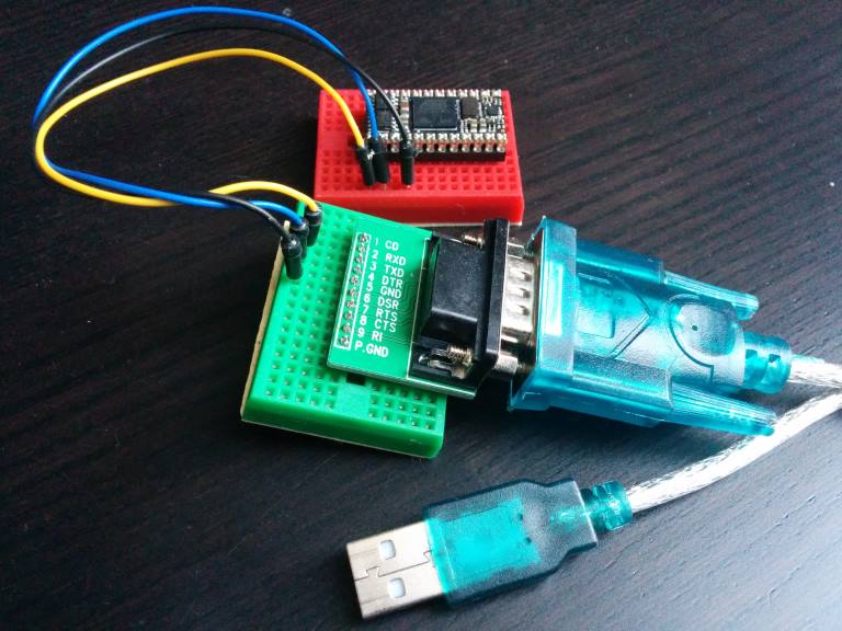
One of the biggest problems is that I have to pry the Netduino Mini off the pcb, and put it into this setup. Then I program it, and put it back on my pcb. Tedious to say the least.
So now I'm on a quest to extend my the circuitry on my pcb to include whatever I need to make programming the Netduino easier. My dream is to just be able to connect a micro USB cable to my pcb, and program the Mini that way. Exactly like I'm used to from the Netduino 2 board.
I don't want to use any "special" cables or breakoutboards. Just my laptop, a regular micro USB cable and my custom PCB. And so begins my quest to find some IC's to put on my board to make this happen.
It seems like the Netduino is pretty tolerant of the actual voltage levels of the RS-232 signals. It doesn't have to be -12V/+12. It seems like any voltage from 0V and below is treated as logical high, while somewhere around +2V is interpreted as logical low.
I haven't found any single chip which converts directly from USB to RS-232, but only from USB to TTL levels.
And as I understand it TTL and RS-232 have opposite opinions of what a "high" and a "low" is. So that is why I add the inverter.
So out from the USB-to-TTL chip (the FT232RL) I get 5V for "high", and 0V for "low". It needs to become a zero-to-negative voltage for "high", and +2V-and-up for "low". And that's where I've been told the SN74LVC2G14DBVR should be good enough.
Yes, much clearer now. Look carefully at the schematic of the netduino, it uses an ADM3101 chip to convert from RS232 levels to 3.3V TTL. Don´t think the ARM chip can handle such voltage levels, it is the only the ADM3101 that can handle that.
Now, on your board you would use just for example FT232RL get the USB connection. If you really are using the RS232 from the netdino to connect to other devices, then you would want some way to switch between the ADM3101 which goes to outer world, or the FT232RL to program the chip and communicate with PC, for example using jumpers or zero ohm reistors.
If you don´t need the RS232, then the FT232RL is all you need.
Yes, much clearer now. Look carefully at the schematic of the netduino, it uses an ADM3101 chip to convert from RS232 levels to 3.3V TTL. Don´t think the ARM chip can handle such voltage levels, it is the only the ADM3101 that can handle that.
So - let me add to the confusion again. The Netduino Mini has BOTH an RS-232 input (pins 1-3), and a TTL input (pins 11-12). Both can be used for programming it, but only the RS-232 can be used for changing bootloader. I believe the ADM3101 you see in the schematic is related to the TTL inputs.
I'm targeting the RS-232 pins, not the TTL pins.
This will also have the added benefit of freeing up pins 11-12 as GPIO's. Pins 1-3 cannot have any other purpose than RS-232.
As far as I can see on the photo you are using pins 1,2 and 4 of the netduino. The schematic shows pins 1 and 2 connected to the ADM3101 and then to pins G3 and H2 on the ARM, pin 4 is ground. Pins 11 adn 12 on the netduino are connected to J3 and J4 on the ARM.
So the AMD3101 is connected to the RS232 inputs, because it an RS232 to TTL converter.
But it still means that I have to supply RS-232 level's, since I have to pass the signal through the ADM3101.
So in my mind I'm still at the point where my circuit needs to go from USB to RS-232. If I only have an FT232RL I'll end up sending high's instead of low's to the ADM3101.
Forgive me if I'm not getting it - this is confusing
So you just want a new board that will connect to the netduino? I thought you were meaking a whole new board with both the ARM chip and usb connector on it.
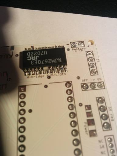
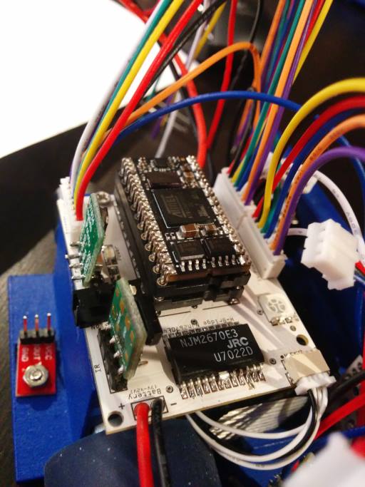
The board I'm making contains the Mini. In the center of the board I've got a 24-pin socket for it, and surrounding it I've got a motordriver, connectors to ir sensors, rgb led, 5V regulator, battery connector etc.
So the Mini is in a 24-pin socket in the center of the board.
Here are two pictures from the first prototype.
Before components are in place:
After components are in place:
As you can see the Mini has TWO sockets underneath it. I've soldered the bottom one to the board, and whenever I need to reprogram the Mini I have to pry the two sockets apart. The top socket is there so that I don't break the legs on the Mini.
So instead of this routine I want to just plug a micro USB cable directly to this board.
The way I want :
89S52 (Tx/Rx) ←→ (Rx/Tx) CP2102 (+D,-D) ←→ (-D,+D) PC USB
If I can buy the FT230RL, I also like to use it.
The easy way you can do :
Netduino mini (Tx/Rx) ←→ (Rx/Tx) FT230RL (+D,-D) ←→ (-D,+D) PC USB
PC USB (-D,+D) ←→ (+D,-D) FT230RL (Rx/Tx) ←→ (Tx/Rx) Netduino mini
USBDP : plus +D
USBDM : minus -D

 Facebook
 Google
 GitHub
 Linkedin



 I'll try to make things a bit clearer.