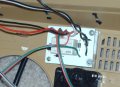
Okay I have been invited to Reginals with the IPMS. I'm going to put this guy in KING TIGER 313. That is where I will introduce the TC. I would indeed like to have your name up on the ID Plate I use for the tank, if that is okay with you. Iended up having to use a bit of cloth around the arm socket. However at the right angle it is hard to see.
I reviewed the test video and see that it seems like I did it all. We know that is the furthest thing from the truth. In my excietment I neglected to mention all the help you gave me in this project. It was not intentional. I wanted all the mistakes to be mine alone as the development progressed.
Without your kind help none of this would have ever happened. I learned more from doing this project than I did in 20 years in submarines and I owe that to you.
The RC tank that will carry the Working talking Tank Commander is almost done. When it is complete the video will begin with a testimony of all the help you gave and the patience you had for me and the project.
You are a kind hearted master of electrons and where they should go to make something work, and if I in any way shape or form offended you I do offer my apology.
Sarge never had more fun in a long time. I've done better than mention this forum, I'm adding both a big thank you to you and this forum and putting a link on my new web site www.tankerslounge.com. Look out guys! You'll have more RC tankers, submariners, RC blimp pilots asking a ton of questions.
Everyone on here is really top shelf, and for folks like me nothing like the working tank commander would have been possible. I just remember what JFK said about going to the moon. "We do not do it because it is easy, but because it is hard."
Almost there! I can almost taste it I'm so close. However I need your help and advise.
The motor I was using was just to long to work, so I fashioned a gear head from one of the old turret rotation motors.
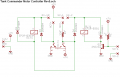
However when I went to put her all back together I kindaforgot how to wire the remote into the circuit. The remote reciever has a + - Comm NO and NC
I know the connection for the RX-18 goes to the COMM, but that is where I am lost again. If you could show me a basic sketch of how to wire it to the remote that would be a great help. I get confused on where the power comes in. From the Remote or from the board.
And just to clear up something in my own mind. On the board does Ground mean NEG?
Once again Wookie you are tops and i sure thank you forall you have done!
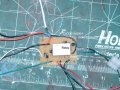
I built another of the circuits, actually two. They are carbon copies, however The relay is switching but I get no power to the motor, on either unit. Seems the same problem on both new boards. The board that was working blew when I incorrectly connected the remote.
If you could help me out I sure would appreciate it.
Almost there! I can almost taste it I'm so close. However I need your help and advise.
The motor I was using was just to long to work, so I fashioned a gear head from one of the old turret rotation motors.
However when I went to put her all back together I kindaforgot how to wire the remote into the circuit. The remote reciever has a + - Comm NO and NC
I know the connection for the RX-18 goes to the COMM, but that is where I am lost again. If you could show me a basic sketch of how to wire it to the remote that would be a great help. I get confused on where the power comes in. From the Remote or from the board.
And just to clear up something in my own mind. On the board does Ground mean NEG?
Once again Wookie you are tops and i sure thank you forall you have done!
I don't know which board version you're talking about now.
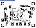
Did you iron the parts transfer to the top of the board like I suggested before? That would be a big help to identify them.
Anyway, post an image of the top and bottoms of the boards so I can verify which versions you are working with. This will help to eliminate mistakes.
[eta]
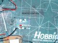
It looks like you painted the top of the circuit board white instead of using the parts mask that I posted. That makes things a bit tougher on both of us.
Anyway, post a photo of the board - with the wires out of the way so we can see the components clearly.
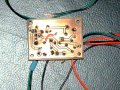
Yes sir it is the same remote. I had to working fine for the test video. However when I got everything in the tank for final installation, I forgot how to wire it up. Then when I did think I had it, the board blew (traces) So I built the board you see in the picture, however this board does not work. The relay will click but I get no power to the motor.
I tested the board without the remote and it still gives no power to the motor.
Hey Sarge I figured it out and got it going. When I Xfered the traces to the board for etching the trace for the motor negative did not Xfer in just a tiny little area. I found the Open when I was using the meter to check voltage. I put in a small jumper so as not to damage other traces and now it is working.
All that remains is your guidance in hooking it to the remote control.
Hey Sarge I figured it out and got it going. When I Xfered the traces to the board for etching the trace for the motor negative did not Xfer in just a tiny little area. I found the Open when I was using the meter to check voltage. I put in a small jumper so as not to damage other traces and now it is working.
It would have been hard for me to figure it out from the photo you posted. You used a flash, and that makes for very harsh lighting.
Use diffused lighting when taking photos. The very best light is outside on an overcast day. If it's bright and sunny, you might fake it by draping a white sheet over yourself and the subject to diffuse the light.
All that remains is your guidance in hooking it to the remote control.
I think this has been covered before. However, the pad marked RX-18 needs to get connected to the battery positive terminal (via a fuse, of course) momentarily in order to start the sequence.

 Facebook
 Google
 GitHub
 Linkedin