Hi ,
My main board works now, there is Q5 was broken, and I redid some soldering on the smd in particular on the resistance R22 which did not make good contact and a leg 1 of U3, I replaced the STRW6251 by a STRW6253 which accepts 10 A.
the engine runs again, the led flashes regularly when you press start and remains fixed when you press stop. The bench is fixed, thanks for the info, and the diagrams of the main board.
I will post a video in few minutes .
Hello, After a short circuit on IGBT, don't feel the step on the belt. / I strongly think this shortcut made a spike on the earth wire and partly damaged the controller. I also post on the Hungarian electronics site, and similar problems were reported thereafter the IGBT short circuit. / Every step on the belt will slower the motor. If I disconnect the speed sensor don't happens anything. I basically fixing an EU-type treadmill, with TWI between the 2 controllers. I don't know, this calibrates the impulse wide from the speed sensor or the increased motor current?
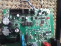
Firstly just 'Cheers' to everybody advising in this thread, found my fault and repair of a 240V MC2100E RevC Icon 2003 by scrolling through from the 1st post..
In passing D8 & D7 on that board aren't 1N4744 & 1N4007 packaging but SMA packs, I had to replace D8 the 15V Zener, Z15SMA15 along with the IRG4PC40K, S8025L & TO3052'''
Popped photo below....
Hi,
I would like to contribute to this excellent site my reverse engineered information for the MC2100ELS-18W controller card. I was asked to "repair" a treadmill which had this card. The first problem was the shorted control "transistor" IRG4PC. This was locally available but on replacing there was a flash-over along the glue for the paper label which took out the micro-processor! A new card was purchased, different component lay-out but the same circuit except for an additional capacitor in series with the original connected between the 2 different system zero volts. No problems encountered with the new card although being an old school systems design engineer I do not like the control system. It appears there is no feedback when there is somebody using the treadmill, the speed varies too much for me. Yes the belt speed sensor appears to be working.
Anyway I trust somebody has a use for the information.
Any faults please advise and I will correct. There are some Zero ohm surface mount resistors which seem a little strange for me.
i have a proform treadmill wich uses MC2100ELS-18W board. While running the motor suddenly achieved a full speed and the breaker switch turns off. When checked, i found the MOSFET faulty. Replaced it. But when ever power is given the mosfet immediately blows off and motor runs at full speed and the breaker switch turns off. Again i examined and found two 200 ohm resistors at the gate of MOSFET were also blown. But changing them along with MOSFET doesn't help. While powered, the same happened. Please help.
One mistake in the posting. The burned out part was G4PC40K which is an INSULATED GATE BIPOLAR TRANSISTOR
Debated whether to post here or start a new thread - decided for here.
I have an MC2100ELS in a Nordictrack T9.2 treadmill that is misbehaving (we bought it faulty hoping to repair it). I am in the UK so we have 240V ac. My board looks identical to the one in this post. Also Max Headroom's post here was enormously helpful (found thanks to Google); although not the same model you'd be surprised just how much is the same. Yes mine has an IGBT (switching on the high side of the motor) - but the current limiting and voltage monitoring circuits seem identical (see my sketch of the power side attached below).
Key questions: - Does the 240V version treadmill have a different motor to the 110V?
- What is the current limit from the MC2100ELS supposed to be?
Symptoms:
- The treadmill appears to function perfectly until you stand on it, at which point the motor torque is not high enough to move the belt - the belt (and motor) is very easy to stall.
- Someone (lacking competence) has had it apart before. The rubber drive belt was lubricated! Also the motor has been messed with; one of the securing bolts had been replaced with the wrong part, motor wires were fixed with different cable ties to the rest of the unit, motor wires touching the running belt. Running belt tension was very loose (the belt drive roller would slip, you could get your whole arm under the walking belt). Many screws for the plastic trim are missing or their moulded posts broken.
Test kit:
- Digital Multimeter, Current measurement resistor (0.33R), stopwatch on mobile phone, measuring tape
Tests performed:
- Motor OK. Dismantled/checked/cleaned, windings not burnt out, good brushes, magnets seem to have good strength. will run well directly from 24V (two car batteries) and pulling around 16A, the treadmill can be walked on fine. (This test found the lubricated drive belt as initially the multirib drive belt pulleys just slipped.) Motor functions as a generator; can record a voltage from its terminals, when attempting to turn the walking belt, also shorting the motor wires give an increase in mechanical resistance to turning the belt.
- Mechanically it seems fine, bearings all seem good, walking belt seems sufficiently lubricated.
- Controller LED functions as expected, no error codes (lit constantly when powered up, flashing regularly when belt running)
- Reed switch working (checked with multimeter vs magnet). Unplugging the speed sensor (reed switch) doesn't do much!
- Calibration seems excellent, running the treadmill through its different speeds (and timing the running belt rotations with a stopwatch and bit of tape) shows it to be within 0.5km/h on all speeds, it's probably out just by my measurement error (full measurements on attachment below)
- Controller output/input to the motor (on a multimeter) without attempting to walk on the belt varies from 8.8V/1.56A at 1km/h to 113V/2.7A at 20km/h. Attempted the same with reed switch disconnected, 120V maximum recorded (full measurements on attachment below)
- Stall current at all speeds (with 0.33R measurement resistor in series with motor) around 4A
- High voltage bus (across two power capacitors) monitored, drops to around 320V when motor accelerating belt, climbs to around 335V when motor unloaded. (The thyristor earlier in the circuit only allows power to reach the capacitors when a speed is selected on the treadmill controls.)
- Voltage across the 0.01R current monitoring resistor monitored, managed to record 0.05V (so 5A) at stall (without my 0.33R current measurement resistor in series with the motor).
- Shorting link placed across 0.0R current monitoring resistor (attempting to remove any current limiting). Can successfully walk on the treadmill! IGBT gets warm while walking on the belt. Also speed regulation seems poor. Although this "bodge" "works", I don't want to run it this way if there's another fault, as it removes the MCU protection for over-current situations.
Suspicions:
(1) Has it got a US motor in it when it should have a UK one? We've not been able to find a photo of a "UK model" motor but most UK treadmills seem to have 180V DC (or higher) motors, ours is rated at 130V (part# F-316708) - and it has clearly been "out" at some point. The seller repeatedly claimed it to have a faulty motor, as if he knew something. Had he swapped the motor for an incorrect one bought on ebay (from the US) that is for a 110V spec treadmill? (And then calibrated the treadmill correctly)? We asked Icon, the chap we spoke to said they'd definitely be different part numbers for US and UK motors, but he didn't know the spec. of them.
(From the equation of force on a conductor, F=BLi, for fixed B [permanent magnets] and a fixed current limit i from the controller, a 240V motor will have more windings of thinner wire, hence more L, thus produce more force F - and more torque.)
(2) Is the controller not producing enough current (and if so, what is faulty)? (Again from F=BLi, output force [torque] is proportional to current.) The bridge rectifier (gbj25m) and thyristor (s8025l) are both rated at 25A, the mains input filter at 10A, the IGBT (g4pc40k) at 25A (100degC) or 42A (25degC). This seems overkill if the currents I am measuring are correct. The controller runs cold (except when I've shorted the current measurement resistor).
The treadmill is rated at 1500W (6.25A input). The motor is rated at "2.75HP Cont Duty @ 130V/2052WATTS" - 2kW at 130V is 15A. Also this video on Youtube (on diagnosing the LED blink pattern) from Icon (the treadmill manufacturer) says the controller will go into a protection mode if the current exceeds 34A. Again currents way higher than what I've measured.
The voltage across the power capacitors seems OK and I see no sign of capacitor failure. The current measurement resistor seems OK (it's not gone high Z) and shorting it seems to partly solve the issue, so does this point to the IGBT? I'm no IGBT expert, can one fail in a way that it goes high-resistance and prevents current flow? Can it's gain reduce like a failed regular NPN/PNP transistor, reducing the expected current throughput vs its drive input? (I think I should just load the parts cannon and just swap it, but I'm unsure!) But the treadmill appears to work well (perfectly) when the belt is not loaded...
Alternatively has something gone wrong in the current limiting control circuit? It's just 2Rs/2Cs going to pin 4 of the MCU (along with the big 0.01R current sensing resistor) so there's not much to go wrong surely? (Annoyingly they are small SMT parts and I don't have the best soldering iron for dealing with SMT stuff - although I've worked with SMT before at previous jobs.)
IGBTs have several failure modes but commonly shorted collector-emitter (over-current or voltage spike) or shorted gate-emitter (gate voltage spike or failed gate driver). From your symptoms its unlikely that the IGBT or gate driver has failed. More likely its in the load (current) sensing section, as you suspect. This part goes into an analog pin on the MCU - a failed component (R or C) would undoubtedly disrupt the analog signal.
Hi all,
I have a main board to repare, it’s mc2100ELS-18-2y REV-
I tested the circuit in my table , just connected with the power cord, 230V .
the led lights up strongly at the start then decreases in intensity and remains lit weakly, there is 5V and the 9v and after a few seconds, the voltages drop to less than 1V, do you have any idea of the failure?
thanks you
This version of the MC2100 uses a switch mode power supply, the secondary is regulated to 9V then from there a 5V regulatore is used. If your 9V rail is failing the fault it is in the switch mode circuit, either on the primary side or on the secondary feedback side which uses a TL431 (U6) and optocoupler (U4) in the feedback loop. The primary switching regulator is U3. CAUTION: the primary-side voltage will be 318VDC - deadly to the unskilled or unwary.
You are correct with the value of R60 it should be 10K. I also unsoldered R53 to check the actual value and it is 1Meg. The colour coding is not what I remember from many years ago, Br, Bl, Gr used to be 1Meg. I also rechecked the component list and corrected R43 and R47, (copy and paste problems).
If the system is shutting down due to over-current then something is wrong. Is anything getting hot to touch?
I mentioned there could be 2 ways for protection from over-current:-
1 Pin 6 of U10, if you check the data sheet, is current protection, Cs.
2 Actual current, measured by R63, is sent to the processor (pin 4) and also could control the PWM to the drive controller (sheet 7 pin 8), U10.
If you really want to change the feedback current, this is on your own head, then a potentiometer across R63, with the wiper connected to R60, would allow you the vary the feedback.
Good luck.
I have attached a new version of the components list and corrected drawing sheet 2.
JBG - I have used your excellent schematic to fix an MC2100ELS-18W board, thanks again for your hard work. In the process of fixing (details in another post) I came across some anomalies in your schematic. Attached is an edited schematic - please verify my changes and update and re-publish your master copy if needs be. There is always the possibility that my board is at a different rev level than yours.
Details of MC2100ELS-18W repair
To maintain this excellent knowledgebase of MC2100 information here's my contribution on fault-finding and repairing an MC2100ELS-18W pcb (230Vac version).
Firstly, thanks to JohnnyBeGood who posted an excellent reverse-engineered schematic of this version of the MC2100 here. There were some minor updates subsequent to his initial post. During my fault-finding and repair efforts I came across some discrepancies between my version of pcb and his original schematic - see my separate post. To the details of my faulty board: the fault symptoms on this board were that the LED blinked 8 times then a pause then 8 blinks again soon after I applied a PWM signal. I had removed the PCB from the TM and powered it up on the bench using 230Vac. I also supplied the 20Hz PWM signal using a function generator into the PWM pin HD2/pin4. (NOTE: if you use a function gen for the PWM input make sure it has sufficient drive capability to source about 20mA. Also ENSURE that you are not over-driving the PWM optocoupler LED - there is only a 22ohm resistor in series with the LED on the board. Limit the function gen output square wave to approx 3V peak, alternatively add a 680ohm resistor in series with your generator's output. Also make sure the DC offset is set so the square wave minimum does not go lower than 0V).
I used a 230Vac 20W bulb across the motor connections - there was no power going to the bulb, only the LED 8 blinks. After quite some fault-finding I found the following problems:
the IGBT IRG4PC40K had gate shorted to emitter - I replaced with an STGW20NC60VD
as a precaution I replaced the IGBT driver U10, an IRS2127
I also replaced the SCR S8025L with a 2N6509G as well as its driver MOC3052
None of the above solved the problem, the LED still blinked 8 times repeatedly. Further debugging finally revealed another problem. Resistor R52 (1Mohm just below the right hand big cap in the photo) was open circuit and prevented the uC from detecting the HV bus voltage at the cathode of SCR Q3.
This was the root cause of the 8 blinks - no information that I could find on the interweb pointed to this fault code or its cause. So this is the fault code for absence of HV bus voltage or faulty HV detector circuit. Replacing R52 as well as the IGBT fixed the pcb. The bulb brightness now varies as I adjust the PWM on the function gen.
Next - re-install and connect to motor and upper control pcb, and calibrate the speed pot. I will report any further findings here.
Hopefully this will be of use to others down the line.
I have a Proform 905ZLT (model PETL11810.1). The board is a MC2100ELS_18W.
The treadmill has been left in the garden by my neighbour and has been given to me before trashing it out. When I plugged it to AC 220V, everything was working, but there was a lot of rust in all the visible metal parts. I disassembled the frame, the rollers. I took off the rust, greased the ball bearing and sprayed all the frame and rollers. Before a complete reassemble, I connected the console to the main board, but the console didn’t switch on. I cleaned the main board with alcohol isopropyl, reconnected again, so the display in the console started working. I tested the inclination, and it was working. The walking belt motor didn’t move when selecting different speed. I’ve tried with the motor engaged to the front roller only (the magnetic sensor is in the right position) and without engaging the motor to the belt. The display shows the selected speed. The LED board is blinking when I press start and change speed. It’s fixed on when stopping. The motor works when connected to a drill battery. If I connect the motor terminals to a bulb, it doesn’t light. But if I disconnect the motor or the bulb and press start, the LED doesn’t blink (so I presume that the board is sensing the load of the motor or the bulb). If I measure the voltage at the motor terminals when is connected and the speed selected, there is no voltage at the terminals.
I was thinking at the IGBT Q6 and I tested with the multimeter 330KΩ and 293KΩ. So to IGBT is not shorted, and I would like to understand how to check the IGBT driving circuit.
I tested with the multimeter all the diodes, the big resistors and the big capacitors, and they seem in the right range.
 Facebook
 Google
 GitHub
 Linkedin