Debated whether to post here or start a new thread - decided for here.
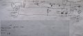
I have an MC2100ELS in a Nordictrack T9.2 treadmill that is misbehaving (we bought it faulty hoping to repair it). I am in the UK so we have 240V ac. My board looks identical to the one in this post. Also Max Headroom's post here was enormously helpful (found thanks to Google); although not the same model you'd be surprised just how much is the same. Yes mine has an IGBT (switching on the high side of the motor) - but the current limiting and voltage monitoring circuits seem identical (see my sketch of the power side attached below).
Key questions: - Does the 240V version treadmill have a different motor to the 110V?
- What is the current limit from the MC2100ELS supposed to be?
Symptoms:
- The treadmill appears to function perfectly until you stand on it, at which point the motor torque is not high enough to move the belt - the belt (and motor) is very easy to stall.
- Someone (lacking competence) has had it apart before. The rubber drive belt was lubricated! Also the motor has been messed with; one of the securing bolts had been replaced with the wrong part, motor wires were fixed with different cable ties to the rest of the unit, motor wires touching the running belt. Running belt tension was very loose (the belt drive roller would slip, you could get your whole arm under the walking belt). Many screws for the plastic trim are missing or their moulded posts broken.
Test kit:
- Digital Multimeter, Current measurement resistor (0.33R), stopwatch on mobile phone, measuring tape
Tests performed:
- Motor OK. Dismantled/checked/cleaned, windings not burnt out, good brushes, magnets seem to have good strength. will run well directly from 24V (two car batteries) and pulling around 16A, the treadmill can be walked on fine. (This test found the lubricated drive belt as initially the multirib drive belt pulleys just slipped.) Motor functions as a generator; can record a voltage from its terminals, when attempting to turn the walking belt, also shorting the motor wires give an increase in mechanical resistance to turning the belt.
- Mechanically it seems fine, bearings all seem good, walking belt seems sufficiently lubricated.
- Controller LED functions as expected, no error codes (lit constantly when powered up, flashing regularly when belt running)
- Reed switch working (checked with multimeter vs magnet). Unplugging the speed sensor (reed switch) doesn't do much!
- Calibration seems excellent, running the treadmill through its different speeds (and timing the running belt rotations with a stopwatch and bit of tape) shows it to be within 0.5km/h on all speeds, it's probably out just by my measurement error (full measurements on attachment below)
- Controller output/input to the motor (on a multimeter) without attempting to walk on the belt varies from 8.8V/1.56A at 1km/h to 113V/2.7A at 20km/h. Attempted the same with reed switch disconnected, 120V maximum recorded (full measurements on attachment below)
- Stall current at all speeds (with 0.33R measurement resistor in series with motor) around 4A
- High voltage bus (across two power capacitors) monitored, drops to around 320V when motor accelerating belt, climbs to around 335V when motor unloaded. (The thyristor earlier in the circuit only allows power to reach the capacitors when a speed is selected on the treadmill controls.)
- Voltage across the 0.01R current monitoring resistor monitored, managed to record 0.05V (so 5A) at stall (without my 0.33R current measurement resistor in series with the motor).
- Shorting link placed across 0.0R current monitoring resistor (attempting to remove any current limiting). Can successfully walk on the treadmill! IGBT gets warm while walking on the belt. Also speed regulation seems poor. Although this "bodge" "works", I don't want to run it this way if there's another fault, as it removes the MCU protection for over-current situations.
Suspicions:
(1) Has it got a US motor in it when it should have a UK one? We've not been able to find a photo of a "UK model" motor but most UK treadmills seem to have 180V DC (or higher) motors, ours is rated at 130V (part# F-316708) - and it has clearly been "out" at some point. The seller repeatedly claimed it to have a faulty motor, as if he knew something. Had he swapped the motor for an incorrect one bought on ebay (from the US) that is for a 110V spec treadmill? (And then calibrated the treadmill correctly)? We asked Icon, the chap we spoke to said they'd definitely be different part numbers for US and UK motors, but he didn't know the spec. of them.
(From the equation of force on a conductor, F=BLi, for fixed B [permanent magnets] and a fixed current limit i from the controller, a 240V motor will have more windings of thinner wire, hence more L, thus produce more force F - and more torque.)
(2) Is the controller not producing enough current (and if so, what is faulty)? (Again from F=BLi, output force [torque] is proportional to current.) The bridge rectifier (gbj25m) and thyristor (s8025l) are both rated at 25A, the mains input filter at 10A, the IGBT (g4pc40k) at 25A (100degC) or 42A (25degC). This seems overkill if the currents I am measuring are correct. The controller runs cold (except when I've shorted the current measurement resistor).
The treadmill is rated at 1500W (6.25A input). The motor is rated at "2.75HP Cont Duty @ 130V/2052WATTS" - 2kW at 130V is 15A. Also this video on Youtube (on diagnosing the LED blink pattern) from Icon (the treadmill manufacturer) says the controller will go into a protection mode if the current exceeds 34A. Again currents way higher than what I've measured.
The voltage across the power capacitors seems OK and I see no sign of capacitor failure. The current measurement resistor seems OK (it's not gone high Z) and shorting it seems to partly solve the issue, so does this point to the IGBT? I'm no IGBT expert, can one fail in a way that it goes high-resistance and prevents current flow? Can it's gain reduce like a failed regular NPN/PNP transistor, reducing the expected current throughput vs its drive input? (I think I should just load the parts cannon and just swap it, but I'm unsure!) But the treadmill appears to work well (perfectly) when the belt is not loaded...
Alternatively has something gone wrong in the current limiting control circuit? It's just 2Rs/2Cs going to pin 4 of the MCU (along with the big 0.01R current sensing resistor) so there's not much to go wrong surely? (Annoyingly they are small SMT parts and I don't have the best soldering iron for dealing with SMT stuff - although I've worked with SMT before at previous jobs.)
Ideally the way to test the motor board is stand-alone using a PWM generator set up into HD2, there are some on Ebay as well as some I made up with a microchip.
This eliminates the processor in the console.
Check voltage on both sides of Q1 WRT Common.
Check signal into and output of U8 MIC4427
Voltage on the output of SCR Q1 should ramp up to B+ voltage in a few seconds of LED blink,
Hi ,
can you tell me how pwm generator is manufactured ?
have you a schema please ?
On the schéma , there is two « in » named IND and INU and i think there is a déphasage on this pwm.
I have a generator signal , it’s good for the test ? Thanks you .
Ok thanks , I connected the board , and there is pwm generated , but that not work ... it‘s same of video ...
I mesured 4,7 4,8 v between pin 3 and 4 of U4 , but 0.5 v between 1 and Gnd.
there is not a pwm on pin4 of U4 ?
Yes I have
I found RG2 Broken... I replaçed and same
I think there is a component who pump the power supply because thé voltage is low on the pin « in » of RG2
Hello everybody, Have anybody schematic for MC2100ELS-50W-2Y board? The problem, The IGBT has become a wire and has not felt the speed sensor since. The signal is going to the uC 19. pin.
 Facebook
 Google
 GitHub
 Linkedin