Marquee Lights - Looking for ideas—can this be done realistically?

MisterBill2

Joined Jan 23, 2018
27,899
Really, consider that a string of 5 or 6 series LEDs will not need a filtered or regulated power supply, but only a reasonably stable supply, such as a transformer with a rectifier. But that would cost more than direct mains power, no question there. BUT an SCR phase controlled supply might be quite cost effective. And the ability to use class "C"wiring could mean a real cost reduction.
 

Thread Starter

robismod

Joined Sep 22, 2015
393
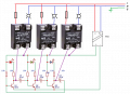
If you are more mechanically oriented, a small gear motor, cam and three lever switches plus the SSRs.

I love the idea of this project, and I hope we can help you complete it.
I hope so too! I’m talking with a top person now about the prospect of it. I feel like if it wasn’t too costly, they would be inclined to go with it. But it’s like other things one tries to convince/sell—It has to be relatively simple operation and bottom line not cost a fortune. (I did like one idea above that recommended looking at those LCD panels…that could make a lot of it very simple and keep lettering tasks on the ground (not on a ladder—I worked there part-time at 15 in 1975 and got up on that ladder to change the letters…no fun LOL)
Maybe, I might have to look at possibly hiring one of you folks to actually design the system and have me install or oversee an installation. But…that could only happen IF I can get them onboard. I think most anyone would agree, the vintage style marquee has a look like no others.
 

MisterBill2

Joined Jan 23, 2018
27,899
I hope so too! I’m talking with a top person now about the prospect of it. I feel like if it wasn’t too costly, they would be inclined to go with it. But it’s like other things one tries to convince/sell—It has to be relatively simple operation and bottom line not cost a fortune. (I did like one idea above that recommended looking at those LCD panels…that could make a lot of it very simple and keep lettering tasks on the ground (not on a ladder—I worked there part-time at 15 in 1975 and got up on that ladder to change the letters…no fun LOL)
Maybe, I might have to look at possibly hiring one of you folks to actually design the system and have me install or oversee an installation. But…that could only happen IF I can get them onboard. I think most anyone would agree, the vintage style marquee has a look like no others.
The very simple scheme is a three bit recirculating shift register driving three solid state relays. OR a CD4017 set to count 0, 1, 2, 0, 1, 2, with a CD4049 hex inverter to drive 3 SSRs, and the other three inverters connected as an oscillator to drive the CD4017.
Certainly that is the very simplest scheme. Note that the 4049 needs to drive the SSRs as a pull-down because it has a greater capability for current sinking.
 

ElectricSpidey

Joined Dec 2, 2017
3,347
How ever you look at it the logic section is going to be really cheap as compared to the light output components.

As such if I were doing this project, I would choose a 556 and the CD4028/29 combo and use one of the 555s to change the direction.

Onward from there is the devil, would probably take some time to decide.
 

Thread Starter

robismod

Joined Sep 22, 2015
393
The very simple scheme is a three bit recirculating shift register driving three solid state relays. OR a CD4017 set to count 0, 1, 2, 0, 1, 2, with a CD4049 hex inverter to drive 3 SSRs, and the other three inverters connected as an oscillator to drive the CD4017.
Certainly that is the very simplest scheme. Note that the 4049 needs to drive the SSRs as a pull-down because it has a greater capability for current sinking.
Wow! I have REALLY jumped into the deep end here, and I don’t know how to swim! I’ll have to carve out some time to study and get my feeble brain to try and grasp your suggestions…(and pull myself away from my little dozer wiring project—1950 IH gas T6 Crawler/dozer that has been consuming my aging brain)
Again, thanks so much for your input and effort.
 

MisterBill2

Joined Jan 23, 2018
27,899
Wow! I have REALLY jumped into the deep end here, and I don’t know how to swim! I’ll have to carve out some time to study and get my feeble brain to try and grasp your suggestions…(and pull myself away from my little dozer wiring project—1950 IH gas T6 Crawler/dozer that has been consuming my aging brain)
Again, thanks so much for your input and effort.
Careful with that IH crawler. My farmer uncles had an IH crawler from that era that would be started on gas and after a warmup be switched over to diesel fuel. THAT changeover is the mystery extra lever towards the right side.
 

ronsimpson

Joined Oct 7, 2019
4,757
Wow! I have REALLY jumped into the deep end here, and I don’t know how to swim!
Look at the picture in post #19. That is close to what you had 50 years ago. Many people would use a computer, but I know you understand how a mechanical switch works. I also have a IH tractor. Think about how a tractor distributor works. In the case of post #19 there are 6 switches, and 6 wheels that the switches follow. Probably each wheel is notched so the switch is closed 50% of the time and open 50%. The wheels are offset 1/6 of a turn.
Another way is to have only one wheel and place the 6 switches evenly around the wheel.
I know that electronics is hard to learn. That is why a mechanical system might be easy for you. Just like the spark and valves work in your IH.
 

ronsimpson

Joined Oct 7, 2019
4,757
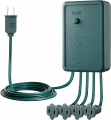
For $30.00 this will make a good demonstration, using 4 lights. (max load is 1.25A or 150 watts) The new bulbs only need 5 to 10 watts to make the old 100W of light.
Many of the LED "dimmable" light bulbs turn off fast. Some turn on too slow but might work. You will need to experiment.
If you need more power, I have some 120V coil, 120/220V 80A relays that will increase the power level.
 

MisterBill2

Joined Jan 23, 2018
27,899
POst #27 Is almost the image of what I was thinking!! Thanks, PM!
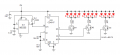
The circuit in post#31 Is quite close to what I tried to describe. So I was not the only one with that sort of idea. Much more efficient than the ring counter i was initially thinking. I think that it was a comment of "Y" that changed my thinking.
 

panic mode

Joined Oct 10, 2011
5,144
i do like the old marquees too. was even thinking to make it with ping-pong balls and LEDs. but have too many things on my plate to just do things for fun.
rather than hardwired logic (gearmotor and cam-switches, gate logic), it is much more flexible to use MCU. a small thing like ESP01, ESP32, RP2040, Arduino or whatever connected to couple of SSRs is all that is needed. old incandescent bulbs had thermal inertia that created those nostalgic fade effects. but LEDs can do the same if convinced... i like the idea of using WiFi to control it, change the speed, do fading, do sudden reversals or whatever feels good on a particular day.
ESP01 is tiny and only has 4 GPIO, ESP32 and RP2040 have more. code is simple, one does not need to write it himself - any AI will easily generate various patterns (chaser, all flash, sparkle, bounce...). as good as it gets to make it plug and play.
Code:
// Vintage Marquee with REALISTIC incandescent fade - 2025 version
// Works on ESP32 or ESP-01, 4–8 channels

#define NUM_CHANNELS 6                     // Change to 4, 6, 8, etc.
const uint8_t pins[NUM_CHANNELS] = {12, 14, 27, 26, 25, 33};  // ESP32 pins

// 0-1000 = brightness level (1000 = fully on)
uint16_t currentLevel[NUM_CHANNELS] = {0};
uint16_t targetLevel[NUM_CHANNELS]  = {0};

unsigned long lastUpdate = 0;
const uint16_t fadeSpeed = 7;   // 3-12 feels most like real bulbs (lower = slower)

void setup() {
  for(int i=0; i<NUM_CHANNELS; i++) {
    pinMode(pins[i], OUTPUT);
    digitalWrite(pins[i], LOW);
  }
}

void loop() {
  unsigned long now = millis();

  // Run the soft-PWM fade engine at ~200 Hz (plenty)
  if (now - lastUpdate >= 5) {
    lastUpdate = now;
    updateFades();
  }

  // ────── Your patterns go here (same logic as before, but now use setChannel() ──────
  static uint8_t mode = 0;
  static unsigned long modeTimer = 0;
  static int step = 0;

  if (now - modeTimer > random(9000, 18000)) {
    mode = random(5);
    modeTimer = now;
    step = 0;
    allOff();
    delay(400);
  }

  switch(mode) {
    case 0: chaser();      break;
    case 1: allFlash();    break;
    case 2: build();       break;
    case 3: sparkle();     break;
    case 4: bounce();      break;   // center-out classic arrow
  }
}

// ────── Pattern examples using the new soft fade system ──────
void chaser() {
  static unsigned long last = 0;
  if (millis() - last > 140 + random(-40,80)) {
    last = millis();
    allOff();
    setChannel(step, 1000);                // full on
    step = (step + 1) % NUM_CHANNELS;
  }
}

void allFlash() {
  static unsigned long last = 0;
  if (millis() - last > 600) {
    last = millis();
    bool on = (millis()/1200) % 2;
    for(int i=0; i<NUM_CHANNELS; i++) setChannel(i, on ? 1000 : 0);
  }
}

void build() {
  static unsigned long last = 0;
  if (millis() - last > 350) {
    last = millis();
    setChannel(step, 1000);
    step++;
    if (step >= NUM_CHANNELS) {
      delay(1000);
      allOff();
      step = 0;
    }
  }
}

void sparkle() {
  static unsigned long last = 0;
  if (millis() - last > 90) {
    last = millis();
    allOff();
    for(int i=0; i<3; i++) {
      setChannel(random(NUM_CHANNELS), random(400,1000));
    }
    delay(70);
  }
}

void bounce() {
  static int pos = 0, dir = 1;
  static unsigned long last = 0;
  if (millis() - last > 110) {
    last = millis();
    allOff();
    setChannel(pos, 1000);
    pos += dir;
    if (pos <= 0 || pos >= NUM_CHANNELS-1) dir = -dir;
  }
}

// ────── Soft-fade engine (the magic) ──────
void updateFades() {
  for(int ch=0; ch<NUM_CHANNELS; ch++) {
    if (currentLevel[ch] < targetLevel[ch]) {
      currentLevel[ch] += fadeSpeed;
      if (currentLevel[ch] > targetLevel[ch]) currentLevel[ch] = targetLevel[ch];
    }
    else if (currentLevel[ch] > targetLevel[ch]) {
      currentLevel[ch] -= fadeSpeed;
      if (currentLevel[ch] < targetLevel[ch]) currentLevel[ch] = targetLevel[ch];
    }
    
    // Simple 1 kHz-ish software PWM on the pin
    bool on = (currentLevel[ch] > (millis() % 1000) * 1000 / 1000);  // cheap dither
    digitalWrite(pins[ch], on ? HIGH : LOW);
  }
}

void setChannel(uint8_t ch, uint16_t level) {
  if (ch < NUM_CHANNELS) targetLevel[ch] = constrain(level, 0, 1000);
}

void allOff() {
  for(int i=0; i<NUM_CHANNELS; i++) setChannel(i, 0);
}
 

MisterBill2

Joined Jan 23, 2018
27,899
It seems to me that it will actually require more than simply an A, B, C sequence, but more like an A+B, B+C, C+D, D+E, EF, F+A sort of sequence, I think that is closer to how the MARQUEE lights ran. Possibly even with three lights on in a group, and with more like three lights off in between. So the wiring would be a bit more complex, and likewise the controls scheme will be slightly more complex. But it will still be quite simple with a few CMOS ICs.
The scheme can use a decimal counter with each group fed by two or three sequential counts. With CMOS there would not be a "fan-out" problem.
 

Ya’akov

Joined Jan 27, 2019
10,274
That was specifying how the lights were wired, not the firing sequence. Just firing the A,B, C, will not result in the illusion of continuous motion in one direction.

@Ya’akov, can you verify?
In fact, traditionally chasing lights do just that—A, B, C(, D) cycles. No special overlapping.

Some even use only two channels, but that gives a much different look. Three channels is the minimum to ensure a smooth look but "fancy" versions use four channels which is even smoother. Adding a fourth channel adds complexity for dubious gain, but it does look better in direct comparison to three.

In either case it is a simple sequential cycle. With two, it moves back and forth, but three makes it seem to progress and four just a little more so.
 

Ya’akov

Joined Jan 27, 2019
10,274
i do like the old marquees too. was even thinking to make it with ping-pong balls and LEDs. but have too many things on my plate to just do things for fun.
rather than hardwired logic (gearmotor and cam-switches, gate logic), it is much more flexible to use MCU. a small thing like ESP01, ESP32, RP2040, Arduino or whatever connected to couple of SSRs is all that is needed. old incandescent bulbs had thermal inertia that created those nostalgic fade effects. but LEDs can do the same if convinced... i like the idea of using WiFi to control it, change the speed, do fading, do sudden reversals or whatever feels good on a particular day.
ESP01 is tiny and only has 4 GPIO, ESP32 and RP2040 have more. code is simple, one does not need to write it himself - any AI will easily generate various patterns (chaser, all flash, sparkle, bounce...). as good as it gets to make it plug and play.
Code:
// Vintage Marquee with REALISTIC incandescent fade - 2025 version
// Works on ESP32 or ESP-01, 4–8 channels

#define NUM_CHANNELS 6                     // Change to 4, 6, 8, etc.
const uint8_t pins[NUM_CHANNELS] = {12, 14, 27, 26, 25, 33};  // ESP32 pins

// 0-1000 = brightness level (1000 = fully on)
uint16_t currentLevel[NUM_CHANNELS] = {0};
uint16_t targetLevel[NUM_CHANNELS]  = {0};

unsigned long lastUpdate = 0;
const uint16_t fadeSpeed = 7;   // 3-12 feels most like real bulbs (lower = slower)

void setup() {
  for(int i=0; i<NUM_CHANNELS; i++) {
    pinMode(pins[i], OUTPUT);
    digitalWrite(pins[i], LOW);
  }
}

void loop() {
  unsigned long now = millis();

  // Run the soft-PWM fade engine at ~200 Hz (plenty)
  if (now - lastUpdate >= 5) {
    lastUpdate = now;
    updateFades();
  }

  // ────── Your patterns go here (same logic as before, but now use setChannel() ──────
  static uint8_t mode = 0;
  static unsigned long modeTimer = 0;
  static int step = 0;

  if (now - modeTimer > random(9000, 18000)) {
    mode = random(5);
    modeTimer = now;
    step = 0;
    allOff();
    delay(400);
  }

  switch(mode) {
    case 0: chaser();      break;
    case 1: allFlash();    break;
    case 2: build();       break;
    case 3: sparkle();     break;
    case 4: bounce();      break;   // center-out classic arrow
  }
}

// ────── Pattern examples using the new soft fade system ──────
void chaser() {
  static unsigned long last = 0;
  if (millis() - last > 140 + random(-40,80)) {
    last = millis();
    allOff();
    setChannel(step, 1000);                // full on
    step = (step + 1) % NUM_CHANNELS;
  }
}

void allFlash() {
  static unsigned long last = 0;
  if (millis() - last > 600) {
    last = millis();
    bool on = (millis()/1200) % 2;
    for(int i=0; i<NUM_CHANNELS; i++) setChannel(i, on ? 1000 : 0);
  }
}

void build() {
  static unsigned long last = 0;
  if (millis() - last > 350) {
    last = millis();
    setChannel(step, 1000);
    step++;
    if (step >= NUM_CHANNELS) {
      delay(1000);
      allOff();
      step = 0;
    }
  }
}

void sparkle() {
  static unsigned long last = 0;
  if (millis() - last > 90) {
    last = millis();
    allOff();
    for(int i=0; i<3; i++) {
      setChannel(random(NUM_CHANNELS), random(400,1000));
    }
    delay(70);
  }
}

void bounce() {
  static int pos = 0, dir = 1;
  static unsigned long last = 0;
  if (millis() - last > 110) {
    last = millis();
    allOff();
    setChannel(pos, 1000);
    pos += dir;
    if (pos <= 0 || pos >= NUM_CHANNELS-1) dir = -dir;
  }
}

// ────── Soft-fade engine (the magic) ──────
void updateFades() {
  for(int ch=0; ch<NUM_CHANNELS; ch++) {
    if (currentLevel[ch] < targetLevel[ch]) {
      currentLevel[ch] += fadeSpeed;
      if (currentLevel[ch] > targetLevel[ch]) currentLevel[ch] = targetLevel[ch];
    }
    else if (currentLevel[ch] > targetLevel[ch]) {
      currentLevel[ch] -= fadeSpeed;
      if (currentLevel[ch] < targetLevel[ch]) currentLevel[ch] = targetLevel[ch];
    }
   
    // Simple 1 kHz-ish software PWM on the pin
    bool on = (currentLevel[ch] > (millis() % 1000) * 1000 / 1000);  // cheap dither
    digitalWrite(pins[ch], on ? HIGH : LOW);
  }
}

void setChannel(uint8_t ch, uint16_t level) {
  if (ch < NUM_CHANNELS) targetLevel[ch] = constrain(level, 0, 1000);
}

void allOff() {
  for(int i=0; i<NUM_CHANNELS; i++) setChannel(i, 0);
}
I was working on a ping pong ball version recently. It *seems* like a good idea but it turns out that ping pong balls are quite dense and just don't want to light up and you might hope. The cheap, "fake" ones can be a little better. The project is on hold but the plan at the moment is to find some plastic bulb LED marquee lights and steal the bulb part.
 
Top