Facebook
 Google
 GitHub
 Linkedin
Hey All,
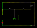
I need to make a SPST momentary switch act like a SPDT switch so thought I could use a PNP transistor for the job. I'm just struggling to understand from my research the correct setup.
I've mocked up a circuit in the falstad circuit editor (link here) which seems to work:

The load I'll be using is different but I've just added an LED + Resistor as POC. The thing I'm unsure of though is if I should need any additional resistors or something around the PNP? All the examples I see have a resistor on the base pin, but I'm not sure if this tends to be more for microcontroller use? I'll be using a physical switch.
Any advice is much appreciated.
Cheers
Matt
I need to make a SPST momentary switch act like a SPDT switch so thought I could use a PNP transistor for the job. I'm just struggling to understand from my research the correct setup.
I've mocked up a circuit in the falstad circuit editor (link here) which seems to work:
The load I'll be using is different but I've just added an LED + Resistor as POC. The thing I'm unsure of though is if I should need any additional resistors or something around the PNP? All the examples I see have a resistor on the base pin, but I'm not sure if this tends to be more for microcontroller use? I'll be using a physical switch.
Any advice is much appreciated.
Cheers
Matt
Attachments
-
 8.9 KB Views: 72
")