Making a multivibrator circuit using LM741

Thread Starter

Petrichor

Joined Dec 19, 2024
36
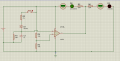
The green LED at the output of the steady-state circuit turns off after 52 ms when a button is pressed, and then the red LED turns on. When the button is released, the red LED turns off after 2 seconds, and the green LED turns on.

I want to make a circuit that meets these conditions using LM741. But I don't know how to make a schematic. Can you help me?
 

WBahn

Joined Mar 31, 2012
32,702
You need to show YOUR best attempt to work YOUR homework problem. We don't work it for you. Show your best attempt and explain your reasoning and what the issues are that you are struggling with. We will help you get over that sticking point so you can continue making progress.
 

Thread Starter

Petrichor

Joined Dec 19, 2024
36
You need to show YOUR best attempt to work YOUR homework problem. We don't work it for you. Show your best attempt and explain your reasoning and what the issues are that you are struggling with. We will help you get over that sticking point so you can continue making progress.
You're right, but I think I asked the question wrong. What I need for the schematic is which components I should use. For example, I'm not sure whether it would make more sense to do this assignment with the LM339 or the LM741. I was just curious about your opinion so I don't waste time fiddling with the wrong components.
 

WBahn

Joined Mar 31, 2012
32,702
You're right, but I think I asked the question wrong. What I need for the schematic is which components I should use. For example, I'm not sure whether it would make more sense to do this assignment with the LM339 or the LM741. I was just curious about your opinion so I don't waste time fiddling with the wrong components.
Wasting time fiddling with the wrong components is actually one of the more effective ways to actually learn something that you will retain.

What is the actual assignment and the actual constraints imposed? Are those the only two ICs that you are allowed to consider? Have you looked at something like a 555?

Start with a simpler problem and see if it gives you some insight. For instance, if you must choose between those two chips, how would you go about making a circuit that went HI upon pressing a button and then went low 100 ms later using each of those?
 

MrAl

Joined Jun 17, 2014
13,667
You're right, but I think I asked the question wrong. What I need for the schematic is which components I should use. For example, I'm not sure whether it would make more sense to do this assignment with the LM339 or the LM741. I was just curious about your opinion so I don't waste time fiddling with the wrong components.
Hi,

Since the output has only two distinct states high or low, I'd start with an LM339 or similar.
You'll then need at least one capacitor and some resistors, possibly a diode or two. It also depends on how complicated the automatic part of the switching action has to be.
Without looking into this too deeply yet, it sounds like what you need is maybe one or two one-shots.

Have you worked with this kind of circuit before, like maybe an oscillator with an op amp or comparator?
 

Thread Starter

Petrichor

Joined Dec 19, 2024
36
Hi,

Since the output has only two distinct states high or low, I'd start with an LM339 or similar.
You'll then need at least one capacitor and some resistors, possibly a diode or two. It also depends on how complicated the automatic part of the switching action has to be.
Without looking into this too deeply yet, it sounds like what you need is maybe one or two one-shots.

Have you worked with this kind of circuit before, like maybe an oscillator with an op amp or comparator?
First of all, thanks for all your responses. I'm familiar with the workings of integrated circuits like opamps, but I've never worked on complex circuits with multiple components. Therefore, I'm having trouble selecting and connecting the circuit components. I'll share a sketch soon so you can better assist me.
 

MrAl

Joined Jun 17, 2014
13,667
First of all, thanks for all your responses. I'm familiar with the workings of integrated circuits like opamps, but I've never worked on complex circuits with multiple components. Therefore, I'm having trouble selecting and connecting the circuit components. I'll share a sketch soon so you can better assist me.
Hi,

Oh that would be good yes.

The LM339 is probably a good choice because you'll need a bistable latch too, and for short delays a comparator should work well also.
So the two delays are 52ms and 2 seconds. If that changes let us know.
 

Thread Starter

Petrichor

Joined Dec 19, 2024
36
I think I've completed most of the circuit. After pressing the button, the green light turns off and the red light turns on. After releasing the button, the red light turns off and the green light turns on 2 seconds later. (I'm not sure of the exact timings; I selected the components experimentally). The circuit works as I want, but I want to measure it to be sure. I tried measuring it with an oscilloscope, but it's quite difficult. Is there another way to do this? Also, could you tell me if you see any flaws in the circuit?
 

Attachments

MrAl

Joined Jun 17, 2014
13,667
I think I've completed most of the circuit. After pressing the button, the green light turns off and the red light turns on. After releasing the button, the red light turns off and the green light turns on 2 seconds later. (I'm not sure of the exact timings; I selected the components experimentally). The circuit works as I want, but I want to measure it to be sure. I tried measuring it with an oscilloscope, but it's quite difficult. Is there another way to do this? Also, could you tell me if you see any flaws in the circuit?
Hi,

What is the problem with using the scope?
Do you have any other test equipment?
You could build a circuit to measure the time periods but it would require some Decade counters and oscillator and stuff like that.

I am not sure if there are any flaws, but you might try connecting the two 220 resistors and LED's in series, then driving the central node with the output of the LM358. So you'd have this:

+Vcc o---GREEN---+---220---x---220---+---RED---o GND

and you would drive the node 'x' between the two 220 Ohm resistors with the output of the LM358.
That's if you want to try it that way and eliminate the transistor.
 

Thread Starter

Petrichor

Joined Dec 19, 2024
36
[QUOTE = "Bay Al, gönderi: 2012841, üye: 241810"]
MERHABA,

Kapsamı kullanmanın sakıncası nedir?
Başka test ekipmanınız var mı?
Zaman periyotlarını ölçmek için bir devre kurabilirsiniz ancak bunun için bazı Onluk sayacı, osilatör ve benzeri şeylere ihtiyacınız olacak.

Herhangi bir kusur olup olmadığından emin değilim, ancak iki adet 220 direnci ve LED'i seri olarak bağlayıp, ardından merkezi düğümü LM358'in çıkışıyla sürmeyi deneyebilirsiniz. Böylece şunu elde edersiniz:

+Vcc o---YEŞİL---+---220---x---220---+---KIRMIZI---o GND

ve LM358'in çıkışıyla iki 220 Ohm'luk direnç arasına 'x' düğümünü sürersiniz.
Tabi eğer siz de aynısını denemek ve transistörü ortadan kaldırmak istiyorsanız.
[/ALINTI]
Osiloskopla ilgili sorun şu: Osiloskopun A ve B kanallarını opamp çıkışına, D kanalını ise toprağa bağlıyorum. Osiloskopun yatay bölümünü 0,5 saniyeye ayarlıyorum. Düğmeyi bıraktığım an ile kırmızı ışığın söndüğü an arasında üç kare görünüyor, yani 1,5 saniye. Ancak gerçekten ölçtüğümde 2 saniye çıkıyor (hesaplamalarıma göre 2 saniye olmalı). Bir diğer sorun da 52 ms'lik bölümü osiloskopla ölçmenin çok zor olması. Başka bir yöntem yok mu?
Bu arada önerdiğiniz yöntemi uyguladım ve daha basit bir devre ortaya çıktı. Teşekkür ederim.

Bir sorum daha var; opamp'ın + girişindeki düğümün voltajını nasıl hesaplayacağımı bilmiyorum. (Voltmetre ile ölçtüğümde orada olmaması gereken bir değer gibi görünüyor.)
 

Attachments

Last edited:

MrAl

Joined Jun 17, 2014
13,667
You should really use English for the replies.
Here is the best translation I can come up with for your reply...

START YOU SAID:
The problem with the oscilloscope is this: I connect channels A and B of the oscilloscope to the op-amp output, and channel D to ground. I set the horizontal section to 0.5 seconds. Between the moment I release the button and the moment the red light turns off, I see three divisions, i.e. 1.5 seconds. But when I actually measure, it comes out to 2 seconds (and according to my calculations, it should be 2 seconds).
Another issue is that measuring the 52 ms section with the oscilloscope is very difficult. Isn’t there another method?
By the way, I applied the method you suggested and a simpler circuit emerged. Thank you.
One more question: I don’t know how to calculate the voltage at the op-amp’s + input node. (When I measure it with a voltmeter, it looks like a value that shouldn’t be there.)
END YOU SAID.

You can try a stopwatch for the 2 second period, but for the 52ms period you probably have to build up a circuit to measure that. Are you up to that task too?
 

Thread Starter

Petrichor

Joined Dec 19, 2024
36
You should really use English for the replies.
Here is the best translation I can come up with for your reply...

START YOU SAID:
The problem with the oscilloscope is this: I connect channels A and B of the oscilloscope to the op-amp output, and channel D to ground. I set the horizontal section to 0.5 seconds. Between the moment I release the button and the moment the red light turns off, I see three divisions, i.e. 1.5 seconds. But when I actually measure, it comes out to 2 seconds (and according to my calculations, it should be 2 seconds).
Another issue is that measuring the 52 ms section with the oscilloscope is very difficult. Isn’t there another method?
By the way, I applied the method you suggested and a simpler circuit emerged. Thank you.
One more question: I don’t know how to calculate the voltage at the op-amp’s + input node. (When I measure it with a voltmeter, it looks like a value that shouldn’t be there.)
END YOU SAID.

You can try a stopwatch for the 2 second period, but for the 52ms period you probably have to build up a circuit to measure that. Are you up to that task too?
I'm sorry, I'm using translation because my English is not good. Sometimes there may be errors.
About the positive input voltage, if you look at the last diagram I uploaded, there is no voltage coming to the +v input node from anywhere when the button is not pressed yet. The capacitor cannot be charged. However, when I measured it with a voltmeter, it showed 2.37v. Is there a different way to calculate the voltage at that node?
And yes, I can build a circuit for the measurement. Just give me a hint about what I should use or the name of the circuit I should build.
 

MrAl

Joined Jun 17, 2014
13,667
I'm sorry, I'm using translation because my English is not good. Sometimes there may be errors.
About the positive input voltage, if you look at the last diagram I uploaded, there is no voltage coming to the +v input node from anywhere when the button is not pressed yet. The capacitor cannot be charged. However, when I measured it with a voltmeter, it showed 2.37v. Is there a different way to calculate the voltage at that node?
And yes, I can build a circuit for the measurement. Just give me a hint about what I should use or the name of the circuit I should build.
Hi,

Place a second 1.8M resistor in parallel to the existing one, then measure the voltage again. Let's see what it drops to.
The only source then looks like it would be the input to the LLM358 which would be bias or leakage current.

The circuit for measuring the pulse time would be similar to a frequency counter. You chain a bunch of decade counters (or binary counters) and then feed it with a crystal oscillator. To measure 0.053 seconds you probably want at least a 100us resolution, which would be 10kHz.
The idea is that the counters are cleared, then the rising edge of the pulse gates the oscillator pulses into the counter string. The oscillator is then gated out when the pulse falled edge occurs. You can have this happen once or keep repeating it.
The best bet is to use counters with output latches. That way you can store the count between test runs.
Because the frequency would be 10kHz it would be good to use 5 decade counters (and 5 latches unless the decade counters include the latches).
You also need a gate, like an AND gate. The oscillator goes to one input of the gate the signal to be measured goes into the other input of the gate.
COST: about $1 USD per counter, plus $1 USD per latch. Oscillator maybe $1 or $2. A gate IC or two maybe $1. Power supply or battery.
You can use 3mm LED's on the output and read off in BCD code unless you want to bother with 7 segment LEDs.
You can probably build this up on a plugboard if you only want it for temporary use.

The alternate is simpler: use a microcontroller. If you use an Arduino UNO or NANO, you can find a ready made program to do this. You download the IDE, program the IC, then use it for your measuring tests. It should be able to handle 53ms easily. You get the readings via the program through the computer you use to program it with.
Cost: about $10USD maybe up to $20USD. Also a small power supply or battery.
You can build this up on a plugboard for the lower frequency like 10kHz.
 

Thread Starter

Petrichor

Joined Dec 19, 2024
36
Hi,

Place a second 1.8M resistor in parallel to the existing one, then measure the voltage again. Let's see what it drops to.
The only source then looks like it would be the input to the LLM358 which would be bias or leakage current.

The circuit for measuring the pulse time would be similar to a frequency counter. You chain a bunch of decade counters (or binary counters) and then feed it with a crystal oscillator. To measure 0.053 seconds you probably want at least a 100us resolution, which would be 10kHz.
The idea is that the counters are cleared, then the rising edge of the pulse gates the oscillator pulses into the counter string. The oscillator is then gated out when the pulse falled edge occurs. You can have this happen once or keep repeating it.
The best bet is to use counters with output latches. That way you can store the count between test runs.
Because the frequency would be 10kHz it would be good to use 5 decade counters (and 5 latches unless the decade counters include the latches).
You also need a gate, like an AND gate. The oscillator goes to one input of the gate the signal to be measured goes into the other input of the gate.
COST: about $1 USD per counter, plus $1 USD per latch. Oscillator maybe $1 or $2. A gate IC or two maybe $1. Power supply or battery.
You can use 3mm LED's on the output and read off in BCD code unless you want to bother with 7 segment LEDs.
You can probably build this up on a plugboard if you only want it for temporary use.

The alternate is simpler: use a microcontroller. If you use an Arduino UNO or NANO, you can find a ready made program to do this. You download the IDE, program the IC, then use it for your measuring tests. It should be able to handle 53ms easily. You get the readings via the program through the computer you use to program it with.
Cost: about $10USD maybe up to $20USD. Also a small power supply or battery.
You can build this up on a plugboard for the lower frequency like 10kHz.
Thanks for your explanation, but I need to measure time in Proteus. I think you told me how to measure in a real circuit.
 

MrAl

Joined Jun 17, 2014
13,667
Thanks for your explanation, but I need to measure time in Proteus. I think you told me how to measure in a real circuit.
Hi,

Oh, haha, I thought you were really building this.

I don't use Proteus maybe someone else can help with that.
Supposedly there is a logic analyzer you can try that.
 
Top