Making an Electronic Weight-Based (Non-Tipping) Rain Gauge

MisterBill2

Joined Jan 23, 2018
27,741
For this very low pressure application a pinch valve is an excellent choice. Really!!
Now all the T needs to do is create an accurate low-range weatherproof, stable, wide temperature range inexpensive load cell and amplifier system. And provide an all-weather housing for the outdoor portion of the system.
 

Thread Starter

wxman

Joined Oct 13, 2022
69
A note on accuracy; Exact precision of the load cell itself is not required. I don't need a load cell that's accurate to the nearest milligram. Because, in reality, I'm not concerned about the "exact weight" of the water. Instead, I would be using the load cell to sense a value range representative of the nearest 0.01" of rain...We're magnifying the rain before measuring, so the sensor can have a certain range of weight error and still be accurate on rain total to the nearest 0.01". The bigger I make the rain gauge, the more magnification and thus the larger the range of possible weight values that can equate to each 0.01".

Example, using an 8 inch diameter catch area, each 0.01" would be 8 grams. 0.02" would be 16 grams....In this case, and considering rounding, my acceptable error range would be +/- 4 grams....Assume exactly 0.01" of rain fell. An exact load cell would measure 8 grams. However, if my load cell measures it as any value between 4 grams and 11 grams, it would still accurately equate to 0.01" rain.

Suppose I increase my catch area to 12 inches in diameter. In that case, that critical 0.01" value would be 18 grams....0.02" would be 36 grams. In that case, my load cell accuracy would need to be within +/- 9 grams. Though a 0.01" rain should equal exactly 18 grams, any value on my scale between 9 grams and 26 grams would accurately report it as 0.01"

I could use a swimming pool as my rain gauge. My scale could probably be +/- 1000 grams error and still report rain accurately to the nearest 0.01", because of the excessive magnification. (In case you're interested, a 7ft diameter pool collects 1000 grams water weight per every 0.01" of rain that falls.)

So what I'm trying to solve here is not "how can I make a cheap load cell accurate to the nearest fraction of a milligram?" I know that's not going to happen. Instead, it's "what's the closest accuracy range I can get with a cheap load cell?", "will this range allow for a reasonably sized rain gauge?" and "if not, what can I do to improve that range as much as possible, so I don't have to resort to using a swimming pool sized rain gauge?"..

I'm hoping a temperature sensor stuck onto the load cell and a simple linear offset based on it's real time value will fix any temperature related error.

For an 8 or 12 inch diameter rain gauge, I would probably use a 5kg (11 lb) or 10kg (22 lb) load cell, such that I'm not maxing it out on weight. That should lower creep rates some. The load cells list creep rates in the format of "X% / Y minutes", but it doesn't tell me much because that's at full scale. I also don't know how long it takes for the creep to level off or if it's going to reactivate when the load increases from adding additional weight (rain).

So I guess what I'm trying to better understand is the behavior of creep/drift on budget load cells and how I can compensate for this to achieve a workable error range. Then I can size my gauge so that each .01" fits within that error range.
 

MisterBill2

Joined Jan 23, 2018
27,741
For those weight ranges, and to avoid load cell aging and drift, probably a good, low friction, wire-wound pot with an arm and a spring will be a better choice. It can have a much greater voltage change over the load range, and be much easier to calibrate. And it will not be nearly as temperature sensitive. Besides that, a really stable voltage regulated supply is much easier than a really stable instrument amplifier, especially with a constant load.
 

Thread Starter

wxman

Joined Oct 13, 2022
69
For those weight ranges, and to avoid load cell aging and drift, probably a good, low friction, wire-wound pot with an arm and a spring will be a better choice. It can have a much greater voltage change over the load range, and be much easier to calibrate. And it will not be nearly as temperature sensitive. Besides that, a really stable voltage regulated supply is much easier than a really stable instrument amplifier, especially with a constant load.
Sounds interesting, though I'm trying to imagine how the spring would adjust the pot. And how much load range I could have. Keeping in mind I would be weighing the collection pipe/container, a solenoid connected to this pipe/container and the water contents inside the pipe. So it may be a constant weight of a few kilograms even before any rain is added, then several grams added for each hundredth of an inch of rain. Would seem to me if it's a very weak spring that changes by the gram, it would be flattened by the intial few kilograms; If it's a strong spring that doesn't move much for the intial few kilograms, then it may not move at all by adding only a few extra grams. Unless I'm misunderstanding something?
 

MrChips

Joined Oct 2, 2009
34,954
"Making an Electronic Weight-Based (Non-Tipping) Rain Gauge"

I don't think the TS wants a "Tipping Bucket" system.
For that same reason, I have stayed away from this thread.
I once had to design battery operated data loggers that had to be lugged deep into caves and left there for 6 months to collect water dripping from stalactites. It measured water temperature, conductivity, and flow rates.
We built our own classic tipping bucket gauges that were simple, repeatable, and reliable.

Every 6 months, a caver had to crawl into the cave, replace the battery with a fresh one, and swap out the SD flash card.
 

Tonyr1084

Joined Sep 24, 2015
9,744
For those weight ranges, and to avoid load cell aging and drift, probably a good, low friction, wire-wound pot with an arm and a spring will be a better choice. It can have a much greater voltage change over the load range, and be much easier to calibrate. And it will not be nearly as temperature sensitive. Besides that, a really stable voltage regulated supply is much easier than a really stable instrument amplifier, especially with a constant load.
Something like this?
View attachment 354396
I would imagine moving the spring could adjust for the weight and hanging the bucket in different locations could adjust for accuracy. Of course this is a crude drawing and further refinements would be needed but this could work. Where you connect the spring, the spring tension and the bucket location all could work together to get a very close setup. From there, use electronics to do the final calibration. It doesn't account for emptying the bucket on schedule.

Small changes in weight is amplified by the length of the beam (not labeled) increasing sensitivity.
 

MrAl

Joined Jun 17, 2014
13,726
Hello again,

You gave me an idea. If something is moving it casts a shadow. I once had an idea to make a very large voltmeter by taking a regular voltmeter and a light source to cast a shadow on the moon (in theory, or just the ceiling in practice). A tiny movement of the needle would make a huge change in the movement of the shadow.

But now we are in the more modern age where cameras are all around. An idea for this project would be to take snapshots of the water that fell into the tank and correlate that data into the water levels and thus the rainfall. A modern microcontroller would probably be able to handle this task. No need for shadows this time unless you care to play around with that idea also.
 

Tonyr1084

Joined Sep 24, 2015
9,744
You gave me an idea. If something is moving it casts a shadow. I once had an idea to make a very large voltmeter by taking a regular voltmeter and a light source to cast a shadow on the moon (in theory, or just the ceiling in practice). A tiny movement of the needle would make a huge change in the movement of the shadow.
I used a small mirror to reflect a laser beam. The mirror sat on my chest and the beam was bounced upon the ceiling. I could watch my pulse and respiration.

I've seen interference wheels from older printers that counted the rotation of the paper feed motor assembly. Something like that could be combined with the drawing above. (post #67)
 

MisterBill2

Joined Jan 23, 2018
27,741
Sounds interesting, though I'm trying to imagine how the spring would adjust the pot. And how much load range I could have. Keeping in mind I would be weighing the collection pipe/container, a solenoid connected to this pipe/container and the water contents inside the pipe. So it may be a constant weight of a few kilograms even before any rain is added, then several grams added for each hundredth of an inch of rain. Would seem to me if it's a very weak spring that changes by the gram, it would be flattened by the intial few kilograms; If it's a strong spring that doesn't move much for the intial few kilograms, then it may not move at all by adding only a few extra grams. Unless I'm misunderstanding something?
OK, and it was my mechanical design experience running wild.
NONE of that heavy plumbing needs to be part of the moving container. Tony provides a fair approximation in post #67. Certainly none of the implementation would be similar to the earlier sketches.
Consider also that using a common load cell with that heavy collection of pieces will require a higher range load cell with the water load being a smaller potion of the measured weight. So with the change being a smaller portion of the load, the demand for accuracy is increased.
 

MikeA

Joined Jan 20, 2013
449
would prefer it to be accurate to the nearest 0.01" inch ....... then flip over to dump the water while triggering a reed switch. It's a simple and low cost design, but accuracy is +/- several percent
This wasn't mentioned yet, I think, but I had concerns about the resolution from the first post. In the non electronic sense.

0.01" = 0.254mm

That is very little. So little that evaporation and surface tension of water would probably account for much more than several percent accuracy, especially when the rain is not intense. Drizzle or light rain would probably barely register with accuracy tens of percent off.
 

MisterBill2

Joined Jan 23, 2018
27,741
OK, my visualization is actually quite different after thinking a bit more. Both simpler and more accurate. The down-side is that it will not measure the RATE of rainfall during the draining periods. Of course, neither will any of the weight measurement systems.
A potentiometer plus a spring that winds up as the pot rotates can be rather repeatable, and made to work without an actual lever. The visualization is difficult to describe without a whole lot of words, is the problem.
 

Thread Starter

wxman

Joined Oct 13, 2022
69
This wasn't mentioned yet, I think, but I had concerns about the resolution from the first post. In the non electronic sense.

0.01" = 0.254mm

That is very little. So little that evaporation and surface tension of water would probably account for much more than several percent accuracy, especially when the rain is not intense. Drizzle or light rain would probably barely register with accuracy tens of percent off.
With all methods, we work around this by using magnification. Keeping in mind that rain totals are "per square inch"... So 0.01"(0.254mm) of rain is only that depth on a ruler if you are using a 1 square inch container to collect the rain.....If you get a wide funnel with a 50 square inch collection area and funnel that into 1 square inch container, you magify the depth 50 times. So that same 0.01"/0.254mm of rain would now measure 0.50" / 12.7mm....That kind of magification is how we're able to read a manual rain gauge with the naked eye to the nearest 0.01" (because each 0.01" tick mark on the magnified inner tube is way more than 0.01" ruler depth apart).....Same process would work with weight (ie. each 0.01" would weigh about 2 grams on a 4 inch diameter rain gauge. It would weigh 8 grams on an 8 inch diameter rain gauge...18 grams on a 12 inch diameter rain gauge)....Bigger the gauge, the more volume of water for each 0.01"

But now we are in the more modern age where cameras are all around. An idea for this project would be to take snapshots of the water that fell into the tank and correlate that data into the water levels and thus the rainfall. A modern microcontroller would probably be able to handle this task. No need for shadows this time unless you care to play around with that idea also.
Actually, I partly use this method right now with my manual rain gauge. I have a pan/tilt/zoom camera that I center into the gauge and watch the water level rise. This is a nighttime example using the camera's white LED and each tick mark being 0.01"....In this example, it's fairly easy to make out that the water level is around 0.27"

1.jpg

But it doesn't always work. Sometimes visibiltiy is too low in heavy rain or fog. Sometimes fog forms all over the outside of the gauge making it impossible to see without wiping it down first. If viewing at an angle, it can distort the perceived position of the water line.

Also, you would need some sort of AI program to automate the process of reading the level within the snapshots. I tried uploading a few pictures like this to ChatGPT and it recognized "this is a rain gauge at night"...But it struggled to read the precise water level. It would say things like "the water level appears a bit above .25" or "between 25 and 30"...It would take a bit of training to perfect it.


NONE of that heavy plumbing needs to be part of the moving container. Tony provides a fair approximation in post #67. Certainly none of the implementation would be similar to the earlier sketches.
Consider also that using a common load cell with that heavy collection of pieces will require a higher range load cell with the water load being a smaller potion of the measured weight. So with the change being a smaller portion of the load, the demand for accuracy is increased.
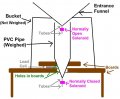
Going back to the original sketch:

weight-rain-gauge1.JPG

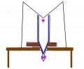
The outer bucket, funnel and entrance solenoid would not be weighed, but I could not weigh the pipe and it's water contents without also weighing the bottom solenoid that's sealed onto the pipe and the mounting board for the pipe (board could be plastic instead of wood to make it lighter)......Weighed area would be highlighted in blue on the next graphic:

weight-rain-gauge3.JPG

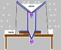
Then if I were to modify to include snow weight without melting, I would have to lower the top funnel and entrance solenoid onto the pipe to be weighed as well, since snow would collect in the top funnel.


weight-rain-gauge6.JPG

I'm definitely intrigued by the potentiometer ideas, and looking at the images that Tony provided gives me a bit more of a feel for it...Though I'm still rather lost as to how I would create such a system with springs and arms. I'm a physics nerd, but definitely not an engineer. So I tend to easily see the physics behind how a device works, but I struggle with the actual building process. In other words, I sort of see how a pivoting arm with increasing weight turns a pot, but not so much how I could buy parts and stick them all together to replicate the process that my mind is invisioning. I know what I WANT the parts to do, but not so much how to force them to actually do it (if that makes any sense?).
 

Thread Starter

wxman

Joined Oct 13, 2022
69
The down-side is that it will not measure the RATE of rainfall during the draining periods. Of course, neither will any of the weight measurement systems.
As long as the emptying process is occasional (maybe once per inch) and doesn't take but seconds to complete, it would not be too big of a deal...

The other possibility is if you can determine the weight drop rate at which the pipe empties, and if you stay in "snow mode" all the time, where you're also measuring the top funnel and it's contents. Your code could adjust for the known weight drop per second as the pipe empties and any additional weight (slower decrease in weight than expected) would be the wight of the new rain that's accumulating in the top funnel....But, like I say, it would not be a deal breaker to go 20 seconds without rate data every once in a while.
 

Werecow

Joined Aug 4, 2025
37
A few questions off the top of my head:

1) Since snow density varies, what information does its weight provide to the system, other than equivalent rainfall -- and is that a useful metric?
2) How much would friction of the snow between the funnel and outer bucket affect accuracy of the readings?
3) How would you propose to keep the system from freezing, and clear the snow between precipitation events?
4) If you're essentially building a DIY strain gauge, why not repurpose the guts from a cheap digital scale?
 

Tonyr1084

Joined Sep 24, 2015
9,744
Yes. a spring connected to an adjusting screw. You tighten or loosen the thumb screw in order to calibrate the scale.
View attachment 354456
The thumb screw (nut actually) can be adjusted to tighten the pull of the spring or it can be loosened to relax the tension on the spring. The flat plate is some sort of mounting bracket. Since I don't have a rig to draw out I just put the flat plate there to indicate what the screw is pulling against. Actually I see a slight mistake; no washer. Oh well. You've stated you want to go back to the weight system. Sorry I couldn't be of more help.
 

Thread Starter

wxman

Joined Oct 13, 2022
69
1) Since snow density varies, what information does its weight provide to the system, other than equivalent rainfall -- and is that a useful metric?
That rainfall equivalent is what I would be aiming for. Then we can use that liquid equivalent with the physical depth of snow on the ground (either manually measured with a ruler or better yet electronically with something like a laser or ultrasonic distance sensor) and then we use those values to calculate the density of snow by means of "physical snow depth to liquid equivalent ratio"..

With a manual gauge, snow accumulates inside the collection bucket. We then bring the bucket inside and weigh the snow on a kitchen scale (or either let it melt and pour into the gauges inner beaker tube) to get the liquid equivalent. Then we go out and measure the depth on the ground with a ruler to get our physical depth. Then divide the values to get the snow/liquid ratio for snow density. It works, but requires a lot of effort, is time consuming and does not give you real time data..

With tipping bucket rain gauges, we wrap the gauge with heated high resistance cable to warm the collection bucket so the snow melts inside the gauge then flows into the tippers like rain. Problem here is 1. The accuracy issues of tipping buckets...2. It can take a while to melt heavy snow using low heat that's barely above freezing...3. If you use high heat to quickly melt the snow, a lot of evaporation/sublimation occurs (tried it and you can actually see steam/fog rising out of the top of the gauge)...

With my proposed design, I would be able to get the liquid equivalent in real time through weight, regardless of snow rate, without having to wait on it to melt or risk evaporation. With a depth sensor (ultrasonic, et.al), I could get a real time depth and let the script calculate my real time snow/liquid ratio.


2) How much would friction of the snow between the funnel and outer bucket affect accuracy of the readings?
That part is a work in progress, but ideally I would make the design to limit the gap between the funnel and outer bucket to limit the amount of rain and snow that reaches the underside of the funnel. This could be done by adding a small downward underhang on the edges of the funnel and the bucket height being higher than that underhand (or something added to the bucket that makes effectively makes it's surface higher than the underhang)...In image below, gray being the underhang wrapping the edges of the funnel that shields precip from the funnel underside.


3) How would you propose to keep the system from freezing, and clear the snow between precipitation events?
All the electronics involved could still operate at below freezing temps (at least as far below freezing as my climate gets, which is usually not much below freezing)...And for snow removal, it's fairly rare in my area so could manually dump it or wait for it to melt on it's own after a day or two. Alternatively, I can wrap the underside of the funnel and inner collection tube with high resistance cable (much like I do to heat the tipping buckets) but only power it with a manual switch after the snow ends and I'm ready to empty.

4) If you're essentially building a DIY strain gauge, why not repurpose the guts from a cheap digital scale?
To my understanding, what I was looking to get essentially was the guts of a cheap digital scale...This is an example of what I was originally plannning:

https://www.amazon.com/ShangHJ-Digital-Weighing-Portable-Electronic/dp/B09VYVRQD5/

Connect one of the load cells to an included HX711 amplifier, then connect the ampt to a microprocessor (such as an Arduino or Raspberry PI)....But compensating for creep with a continuous (but changing) load is where the problem comes in...Taking the guts out of a digital scale should essentially give me the same parts (load cell and amp) with the same drift issues as it's related to the metal of the load cell deforming under constant load.

The suggestions now being made about using a potentiometer, is an alternative way to effectively make a strain gauge while avoiding the data drifts associated with standard cheap load cells.
 
Top