Making an Electronic Weight-Based (Non-Tipping) Rain Gauge

Sensacell

Joined Jun 19, 2012
3,786
You stated before that you are using a "10Kg load cell" which represents 10 liters of water, full scale.
What is the "full tank" weight you are trying to measure?

The thermal drift for a 10Kg load cell might be almost the same as a 1kg load cell.
Trying to use the bottom 10% of the sensor's range will give you 10X the noise, drift and stability troubles.
 

Thread Starter

wxman

Joined Oct 13, 2022
69
You stated before that you are using a "10Kg load cell" which represents 10 liters of water, full scale.
What is the "full tank" weight you are trying to measure?
I'm actually not sure on the tank size just yet. I've been experimenting with a few different sizes, though the final size will largely depend on the drainage system. While I've got a 10kg installed right now, I've also got a 5kg on hand in case I can get by with less and a 20kg in case I need to go larger.

I'm planning to hold at least 1 inch of rain between empties, which with the current size of my entrance, would weight about 3.1kg....Possibly a few inches of rain between empties, depending on my drainage solution.

Keeping in mind, that in addition to the raw water weight, you'd also have to include the weight on the plastic tank, the board I'm using for the top mouting plate for the load cell, the 15.75 inch diameter entrance plate (as that's where snow would get weighed); All of that could easily add at least 1 kg, maybe 2 kg extra.....So a 5kg load cell would be the absolute bare minimum I could get by with, and that would be completely maxing it out. The 10kg load cell gives me a little more wiggle room and the ability to hold 2 to 3 inches of rain before maxing out....The 20kg load cell would allow me to hold closer to 6 inchs before maxing out, but with less precision. So the 10kg seemed like a good balance between precision and storage capacity.

The thermal drift for a 10Kg load cell might be almost the same as a 1kg load cell.
Trying to use the bottom 10% of the sensor's range will give you 10X the noise, drift and stability troubles.
My biggest concern was creep from constant load, which from what I've been told, is more significant on the higher end range of weight. So I was trying to limit the time spent in the higher ranges. With a 10kg load cell, that would put me at 10-20% capacity with an empty gauge and 50% capacity with an inch of rain added. Does that sound reasonable? This is my first experience with a "continuously loaded" load cell, so this is still a learning curve for me.
 

Thread Starter

wxman

Joined Oct 13, 2022
69
What I've done as a temporary test is cover the SHT31 sensor board with rope caulk, leaving only the sensor exposed. Then pressed it onto the side of the load cell. While still not perfect, it's definitely cut back on some of the delay.

load cell temp1.JPG

Doing a scatter plot shows fairly decent linear relationship with a slope change of approx 180 raw values per degree F (scale is roughly 200 raw value per gram, so this equals approx 0.9 gram change per degree F.

load cell temp2.JPG

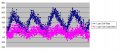
Using that regression as a calibration, this is my raw vs calibrated raw:

load cell temp3.JPG

The calibration definitely lowers the amplitude of the curve (from roughly 250 to between 100-150), though a curve is still there with the amplitudes peaking at different times. Which seems like it could be related to the rate of temp change....

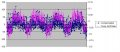
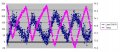
I added a column to my spreadsheet that takes the current temp and subtracts the value from 5 cells higher (ie. 5 observations ago) to get a drift rate. Graphing it in pink alongside my calibrated number (blue) seems to show a strong correlation between the leftover curves and temp change rate suggesting I could benefit from adding a rate term to my calibration:

load cell temp4.JPG
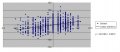
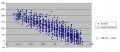
And the scatter plot:

load cell temp5.JPG
I need to test it with bigger temp swings than 1 degree. I may try using a blow dryer for a rapid temp change and see how these equations hold up.
 

MisterBill2

Joined Jan 23, 2018
27,744
What I may have missed while I was gone was if that is a full bridge load cell, or a half bridge load cell, or a quarter bridge load cell. That makes a difference in the temperature related drift rates. AND there is also the temperature driven strain signal change, as the cell body contracts as it cools.
 

Thread Starter

wxman

Joined Oct 13, 2022
69
What I may have missed while I was gone was if that is a full bridge load cell, or a half bridge load cell, or a quarter bridge load cell. That makes a difference in the temperature related drift rates. AND there is also the temperature driven strain signal change, as the cell body contracts as it cools.
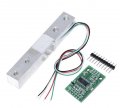
I believe it's a full bridge. It's this 4 wire bar:

loadcell01.jpg
 
Top