
 Facebook
 Google
 GitHub
 Linkedin

Just a thought, take an additional identical load cell and mount it rigidly to a non lexicon part of the collection structure, uses its drift to compensate for the temperature sensitivity of the load cell being used for weighing.1. Temperature compensation. I've got an SHT31 sensor mounted right next to the load cell. But the metal load cell reacts quicker to temp changes than the air, so there's a bit of a lag. One option may be to include some kind of insulation (foam, bubble wrap, etc.) around the load cell and temp sensor so that even a fast change in outdoor air temp gets slowed....Another option is mounting a temp sensor directly to the surface of the load cell. The SHT31 sensor that I have is embedded in a small circuit board that's full of capacitors and other electronics, so it will be difficult to mount that board cirectly to the load cell without the metal shorting out the other electronic components. Perhaps a temp sensor inside a probe would be easier?
Making an Electronic Weight-Based (Non-Tipping) Rain Gauge
- Thread starter wxman
- Start date
Scroll to continue with content

This whole thread is fascinating- Here is a very interesting patent along these lines:
https://patents.google.com/patent/US20180341042A1/en
https://patents.google.com/patent/US20180341042A1/en
Attachments
-
 730.2 KB Views: 5
MisterBill2
- Joined Jan 23, 2018
- 28,253
I have just read thru the past 60 or so posts, since I was gone for a while. An interesting drift towards also measuring snow depth. In my area we sometimes get a fair amount of snow, so I have many years of experience with snow depth. Snow depth varies a whole lot, even in open spaces.
For the rainfall weight measurement scheme, the complexity suggested would offer many points of variability, far greater than what could be achieved with a well constructed dumping bucket scheme.
so I offer a suggestion: create a small volume tipping bucket sensor supported by a load cell mechanism. Then it will be possible to constantly monitor the weight of the water while also getting the volume accumulation measurement. The mechanical complexity will be greatly reduced and the load cell span will also be much less. That is good because not all load cells are perfectly linear. In addition, the sensing of the "actual tip movement" will be noted by the rapid change in the weight signal.
The TS will certainly see that the linearity of the less expensive load cells is not quite as good as the $200 load cell assemblies.
For the rainfall weight measurement scheme, the complexity suggested would offer many points of variability, far greater than what could be achieved with a well constructed dumping bucket scheme.
so I offer a suggestion: create a small volume tipping bucket sensor supported by a load cell mechanism. Then it will be possible to constantly monitor the weight of the water while also getting the volume accumulation measurement. The mechanical complexity will be greatly reduced and the load cell span will also be much less. That is good because not all load cells are perfectly linear. In addition, the sensing of the "actual tip movement" will be noted by the rapid change in the weight signal.
The TS will certainly see that the linearity of the less expensive load cells is not quite as good as the $200 load cell assemblies.
I had initially thought of that, but was looking on a website about temperature compensation of load cells which stated that even exact model load cells can have different amounts of drift per degree of temperature change. The example they tested had several "identical" load cells next to each other with no load present on any. They changed the temperature by a few degrees and each load cell drifted by a different amount (some by only 1 or 2 grams and others as much as 7 grams, if I remember correctly)..Just a thought, take an additional identical load cell and mount it rigidly to a non lexicon part of the collection structure, uses its drift to compensate for the temperature sensitivity of the load cell being used for weighing.
Perhaps there's still a work around using that method by also compensating for the known difference in drift rates between load cells? For easy math, lets say my main load cell drifted 1 gram per degree temp change and my second load cell drifted 2 grams per degree. My formula could take the drift of the second cell and divide by 2, since I knew my main cell drifted by half...
The amplifier I'm using for the load cell is HX711, which has 2 "channels" for connecting 2 different load cells. Though the second channel has a lower gain (32) while the main channel gain is 128...Not sure if that would complicate things or not. If I needed to add a second amplifier for the second load cell, that will require a lot of additional wiring.
The temperature sensor wiring is quite simple as it's I2C, so it can tap into the same multiplexer that I'm using with other I2C sensors and all share the same line back to the Raspberry Pi...The load cell amplifiers are not I2C and require wiring to a dedicated GPIO port on the Raspberry Pi. It's doable as I have extra unused GPIO ports available, but I've already got a crazy amount of wires to deal with. Another amplifier will add 8 additional wires to the already jumbled up mess of wires. Hoping I can avoid having to do that.
Interesting idea. I haven't read through the whole document yet, so perhaps this is already addressed....but my initial question thought was "what happens if the collection bucket fills before it quits raining?" There's got to be some type of "backup collector" in place to temporarily store new rain in a separate location during an emptying phase of the "main collector"...Unless it's a super large main collector that will store several feet of rain without needing to empty (which can happen during a stalled tropical storm/hurricane).This whole thread is fascinating- Here is a very interesting patent along these lines:
https://patents.google.com/patent/US20180341042A1/en
One of the issues with the small volume tipping bucket design is water loss during tips. There's nothing to stop the flow of water when the tippers are emptying/changing position. Granted, it only takes a fraction of a second to complete the tipper change, but in heavy rain, those tippers are contantly flipping back and forth; Sometimes more than once per second. That fraction of a second of water loss multiplied by hundreds of times for hundreds of tips can effectively add up to several seconds worth of water loss...That's a lot of tip losses and why they tend to significantly under report in very heavy rain.I have just read thru the past 60 or so posts, since I was gone for a while. An interesting drift towards also measuring snow depth. In my area we sometimes get a fair amount of snow, so I have many years of experience with snow depth. Snow depth varies a whole lot, even in open spaces.
For the rainfall weight measurement scheme, the complexity suggested would offer many points of variability, far greater than what could be achieved with a well constructed dumping bucket scheme.
so I offer a suggestion: create a small volume tipping bucket sensor supported by a load cell mechanism. Then it will be possible to constantly monitor the weight of the water while also getting the volume accumulation measurement. The mechanical complexity will be greatly reduced and the load cell span will also be much less. That is good because not all load cells are perfectly linear. In addition, the sensing of the "actual tip movement" will be noted by the rapid change in the weight signal.
The TS will certainly see that the linearity of the less expensive load cells is not quite as good as the $200 load cell assemblies.
As far as the non-linear curve of the load cell, my plan was to use a "multi-point calibration curve" for a bunch of different known weight levels to help smooth out the curve. That and the fact that my current design only needs to be accurate to the nearest 31 grams gives me a lot of wiggle room for non-linear imperfections. The main reason for using such a large catch area is so that the weight difference between each significant value is enough that even a very imperfect load cell could still accurately round to the nearest significant value.
MisterBill2
- Joined Jan 23, 2018
- 28,253
Consider that my same post ALSO suggests a load cell monitoring the weight of the whole mechanism. Sp no data would be lost at any time, if the tipping mechanism construction is not terribly crude. In addition, since the instrument amplifier for the load cell really should be close by, all of the temperature compensation circuits can be conveniently close. The additional benefit is getting two readings of the same variable at the same time, in exactly the same location, for very little extra cost.
AND, you get the draining of the collection portion used to measure the weight for no extra complexity.
AND, you get the draining of the collection portion used to measure the weight for no extra complexity.
If we're simply measuring the weight of the tipper with a load cell, then during each tip, weight will be decreasing from the water leaving the tipper while also increasing from new water still entering the tipper. You wouldn't know how much weight was added mid-tip vs. how much was lost. Even if you could, it would take load cell measurements being logged on the order of milliseconds. In my current setup, I have my script set to take 50 measurements, remove outliers, average the remaining values and post that average. I end up with one "average" being posted every few seconds. Data spikes, noise, etc. all make for a wide range of values among the 50 measurements that make up each posted data point, but averaging and removing outliers is what smooths out my data...Consider that my same post ALSO suggests a load cell monitoring the weight of the whole mechanism. Sp no data would be lost at any time, if the tipping mechanism construction is not terribly crude. In addition, since the instrument amplifier for the load cell really should be close by, all of the temperature compensation circuits can be conveniently close. The additional benefit is getting two readings of the same variable at the same time, in exactly the same location, for very little extra cost.
AND, you get the draining of the collection portion used to measure the weight for no extra complexity.
MisterBill2
- Joined Jan 23, 2018
- 28,253
It should be possible to build a "tipper package that would tip about once per minute in a heavy rain, and less often in a light rain, and in any instance just have the transition time crossing the divide at less than one millisecond. It would provide no "data spikes" in the analog weight portion, and uniform pulses in the digital portion. BUT CERTAINLY it would require some adjustment of the software scheme.
It would also avoid the issue of needing to trigger the draining cycles.
It would also avoid the issue of needing to trigger the draining cycles.
With the goals of:
Highest accuracy
High "dynamic range" - the ability to accurately measure both large and light rainfall
Minimum "data quantization" - steps in output data caused by the sampling mechanism
High sample rate - to be able to accurately measure the RATE of rainfall
High system reliability and "certainty"- prevent hidden errors from leaky or stuck valves, etc. Insidious errors that would be hard to detect.
Lowest possible "dead time" - between system drain and reset cycles
Lowest possible drift and temperature coefficient.
https://patents.google.com/patent/US20180341042A1/en
I like this basic concept of two measuring cells that pivot mechanically, to fill and drain alternately.
Add an electro-mechanical, closed-loop servo system that actively tracks the water level, using a capacitive or other sensor to hold a fixed height over the water column.
(must be non-contact to avoid surface tension hysteresis effects)
Track the mechanical position using an encoder following the sensor head - or other direct means to read the water level.
Auto-zero after each tip-out, with some calibration reference at the bottom of the cup.
Highest accuracy
High "dynamic range" - the ability to accurately measure both large and light rainfall
Minimum "data quantization" - steps in output data caused by the sampling mechanism
High sample rate - to be able to accurately measure the RATE of rainfall
High system reliability and "certainty"- prevent hidden errors from leaky or stuck valves, etc. Insidious errors that would be hard to detect.
Lowest possible "dead time" - between system drain and reset cycles
Lowest possible drift and temperature coefficient.
https://patents.google.com/patent/US20180341042A1/en
I like this basic concept of two measuring cells that pivot mechanically, to fill and drain alternately.
Add an electro-mechanical, closed-loop servo system that actively tracks the water level, using a capacitive or other sensor to hold a fixed height over the water column.
(must be non-contact to avoid surface tension hysteresis effects)
Track the mechanical position using an encoder following the sensor head - or other direct means to read the water level.
Auto-zero after each tip-out, with some calibration reference at the bottom of the cup.
MisterBill2
- Joined Jan 23, 2018
- 28,253
Now I see that the one issue that has not been mentioned is the cost and complexity tradeoff. For all of those folks who do not have unlimited funds available, that issue eventually becomes more important.
Given that the TS has several times mentioned the lack of skills to complete different options, it seems to me that there should be some consideration to that aspect of the project.
Given that the TS has several times mentioned the lack of skills to complete different options, it seems to me that there should be some consideration to that aspect of the project.
A lot of great ideas being presented, which are fascinating from a discussion standpoint...But many are not applicable to the current project because they either
1. Would be too costly for a home rain gauge...or
2. Would take more technical skill to construct than your average weather observer has (keep in mind, most weather observers are not engineers; They're often teenagers, retired senior citizens, etc.)...I'm trying to make a simple weighing device that only takes basic skills to construct and operate.
To reiterate the project goals, where I currently stand with the design, what needs improving and the future goals.....
Current approved method for Observers:
My goal:
The requirements:
Basic Needed Parts:
Process:
Considerations:
Issues Not Yet Resolved:
Human Involvement:
Short-Term Future Goal of the Project:
Long Term:
1. Would be too costly for a home rain gauge...or
2. Would take more technical skill to construct than your average weather observer has (keep in mind, most weather observers are not engineers; They're often teenagers, retired senior citizens, etc.)...I'm trying to make a simple weighing device that only takes basic skills to construct and operate.
To reiterate the project goals, where I currently stand with the design, what needs improving and the future goals.....
Current approved method for Observers:
- Collect precip in a plastic container
- Human goes out once/twice a day, gets container and places it on cheap load cell/kitchen scale
- Does basic math to convert the grams into inches (to the nearest hundredth inch)
- Types out those numbers and submits it to a website
- Puts container back out to wait for the next precip event
My goal:
- Automate this same, already approved process so that the data can be shared online instantly (instead of once per day) and without needing daily human intervention
The requirements:
- Low-cost (preferably ~$100 range or less; In line with the general price range of a consumer tipping gauge)
- Simple design that any hobbyist, teenager, senior citizen, etc. can construct at home (No special skills, advanced tools or engineering degree needed)
- Easy-to-obtain parts from the hardware store, internet and/or recycled junk you find in your garage
- A basic computer script (Python) that controls the components, that's easy for the end constructor to edit a few numbers to match the size of components they're using
Basic Needed Parts:
- Micro-computer (Raspberry Pi, Arduino, etc.; Under $30 basic units are fine)
- Some cable/wires
- Cheap load cell
- Drainage system (ie. gravity drain solenoid or water fountain pump)
- Relay (that the script uses to send power to drainage system when needed)
- Outer shell (something like a 5 gallon bucket) to house the compenents
- Slightly smaller internal collection container (1 or 2 gallon bucket, milk jug, detergent bottle, etc.) to store rain
- Wide-mouth entrance used to magnify the "catch area" of the precip, preferrably 8 inch diameter or larger (car oil changing funnel, bowl, top to a bird bath, etc.)
Process:
- Rain enters your wide mouth entrance/funnel and flows into the internal storage container
- Load cell constantly weighing
- Script converting that weight to precip amount and rate, while uploading to the internet
- At a given time interval and/or rain amount, script activates the relay sending power to the drain system to empty the internal collector; Logging data and zeroing the scale as needed
Considerations:
- Wide-mouth entrance/funnel must offer enough magnification to offset the amount of error/drift of the load cell (ie. if your load cell is accurate within 5 grams, your entrance must magnify so that each significant rain value (0.01") weighs more than 10 grams, so that even when your load cell drifts off at it's max error, it's still accurately rounding to the nearest significant value)
- Entrance funnel must be shaped to where it gravity drains into the internal collection container
- Internal collection container needs to be small enough to fit inside the outer shell, but large enough to limit how often it needs emptying to minimize error.
- If using a solenoid for your exit drain, the internal container must be shaped to where it can gravity drain as well; Not necessary if using a fountain pump for drainage
Issues Not Yet Resolved:
- Temperature compensation for the load cell. Current investigative approach is using a temperature sensor, some type of insulation and/or a second unloaded "dummy load cell"
- Ensuring proper gravity drainage of internal container if using the solenoid drain method
- How to handle new rain that falls during an emptying phase...Current investigative approaches:
1. Normally-open solenoid between the entrance and storage container that closes to block flow of new rain during emptying
2. Drain line between entrance and storage container and an air pump to pressurize that line with air, blocking it's water flow during emptying
3. Drainage that occurs at a known, steady rate (ie. X grams per minute) such that the difference between expected rate and actual rate is what's being added by new rain.
- Dealing with wildlife and airbourne debris (birds, squirrels, leaves, sticks, etc.) that can climb/land on your entrance causing weight spikes
1. For a "rain-only" gauge, this is simple; Only weigh the internal storage container and put a filter/strainer between the entrance and internal storage
2. But for the purpose of instantly weighing snow/ice without melting first, that entrance funnel would have to be part of the weighing scheme; Thus subject to wildlife and debris getting weighed...The weight script could be set to remove a sudden, extreme spike that's unrealistic from a rain rate standpoint (ie. a squirrel jumps onto the gauge causing a 1 lb or 0.5kg weight spike in 2 seconds), but some lighter-weight leaves, birds, etc. could make a weight spike equivalent to what's seen in a heavy downpour.
Human Involvement:
- Putting the parts together
- Doing an initial calibration with the help of a script
- Replacing components when something breaks
- Occasional cleaning/removing debris
- Occasional calibration checks by switching the script to a test mode and pouring a few known amounts of water into the gauge to confirm correct readings
Short-Term Future Goal of the Project:
- Open-source design and scripts as a hobbyist project that anyone can build/modify themselves
- Make minor improvements
- Non-commercial, with the exception of maybe making a select few pre-built units for parts/small labor cost for those interested in experimenting but do not have the time or means to construct from scratch; With the disclaimer that it's experimental and without any warranty
Long Term:
- If tests show good performance and reliability over time, then perhaps one day I'll consider a commercialized version with custom 3D printing...We'll see....
Last edited:
Some thoughts:
1. Normally-open solenoid between the entrance and storage container that closes to block flow of new rain during emptying
Solenoids are heavy, Solenoid valves have small ports (unless they are REALLY heavy big ones) that will quickly clog.
They are also massive power hogs when operating. If these are part of the weight payload, they will dilute the weight measurement by quite a bit.
Any tubing or plumbing between the tanks and valves will induce forces into the weight measuring system, corrupting the readings.
2. Drain line between entrance and storage container and an air pump to pressurize that line with air, blocking it's water flow during emptying
So really this serves as a second valve?
If the tube is small enough that a small airflow would block the water coming in, it would create a flow restriction that would cause problems under heavy rain conditions.
3. Drainage that occurs at a known, steady rate (ie. X grams per minute) such that the difference between expected rate and actual rate is what's being added by new rain.
This is very difficult in practice, don't underestimate how hard this would be to achieve.
1. Normally-open solenoid between the entrance and storage container that closes to block flow of new rain during emptying
Solenoids are heavy, Solenoid valves have small ports (unless they are REALLY heavy big ones) that will quickly clog.
They are also massive power hogs when operating. If these are part of the weight payload, they will dilute the weight measurement by quite a bit.
Any tubing or plumbing between the tanks and valves will induce forces into the weight measuring system, corrupting the readings.
2. Drain line between entrance and storage container and an air pump to pressurize that line with air, blocking it's water flow during emptying
So really this serves as a second valve?
If the tube is small enough that a small airflow would block the water coming in, it would create a flow restriction that would cause problems under heavy rain conditions.
3. Drainage that occurs at a known, steady rate (ie. X grams per minute) such that the difference between expected rate and actual rate is what's being added by new rain.
This is very difficult in practice, don't underestimate how hard this would be to achieve.
MisterBill2
- Joined Jan 23, 2018
- 28,253
It is entirely possible to create a set of requirements that push the cost and complexity of a project far past possibility. On some occasions the result is a compromise solutions, while in other instances the result is project cancellation.

panic mode
- Joined Oct 10, 2011
- 5,244
i was skimming over the topic several times waiting for something like post #130.
also i was surprised by topic title imposing limitations... without considering tradeoffs...
tipping is simple, no need for restrictions or orifices that could clog or impede the flow. no need for adding weights (solenoid) or tension (tubing).
and if the desire is to proceed with non-tipping, then perhaps consider alternatives to solenoid.
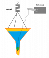
solenoids weigh a lot (and thus throws of measurements). lightweight alternative would be simple check-valve (something like bathtub plug) that is lifted by a servo using fishing line. ball is much smaller and lighter than solenoid and fishing line would be not in tension during measurement.
personally i would rather stick with tipping...
also i was surprised by topic title imposing limitations... without considering tradeoffs...
tipping is simple, no need for restrictions or orifices that could clog or impede the flow. no need for adding weights (solenoid) or tension (tubing).
and if the desire is to proceed with non-tipping, then perhaps consider alternatives to solenoid.
solenoids weigh a lot (and thus throws of measurements). lightweight alternative would be simple check-valve (something like bathtub plug) that is lifted by a servo using fishing line. ball is much smaller and lighter than solenoid and fishing line would be not in tension during measurement.
personally i would rather stick with tipping...
MisterBill2
- Joined Jan 23, 2018
- 28,253
I suggested an interesting arrangement of adding a weighing scheme to a tipping system. It could deliver the best of both. It was quite totally scorned. Evidently some folks are unable to visualize anything. All they can see is that four-dollar tipping device that was very poorly injection molded from 4X regrind plastic waste.i was skimming over the topic several times waiting for something like post #130.
also i was surprised by topic title imposing limitations... without considering tradeoffs...
tipping is simple, no need for restrictions or orifices that could clog or impede the flow. no need for adding weights (solenoid) or tension (tubing).
and if the desire is to proceed with non-tipping, then perhaps consider alternatives to solenoid.
solenoids weigh a lot (and thus throws of measurements). lightweight alternative would be simple check-valve (something like bathtub plug) that is lifted by a servo using fishing line. ball is much smaller and lighter than solenoid and fishing line would be not in tension during measurement.
personally i would rather stick with tipping...
View attachment 356632
Current "normally-closed" solenoid that I've been testing for drainage is this:Some thoughts:
1. Normally-open solenoid between the entrance and storage container that closes to block flow of new rain during emptying
Solenoids are heavy, Solenoid valves have small ports (unless they are REALLY heavy big ones) that will quickly clog.
They are also massive power hogs when operating. If these are part of the weight payload, they will dilute the weight measurement by quite a bit.
Any tubing or plumbing between the tanks and valves will induce forces into the weight measuring system, corrupting the readings.
https://www.amazon.com/DIGITEN-Solenoid-Connect-normally-Pressure/dp/B071JDFVNQ
It's quarter inch opening drains my container fairly fast and it weighs less than the board I'm using as a top plate for the load cell. I'm using a 10kg (22 lbs) load cell, which is really oversized for the project, so I've got plenty of weight range to work with. It uses about 5 watts of power when running (which is only occasionally for a quick minute when emptying). I'm also using screens and filters to prevent any debris from clogging it. Adding an extra one like this to the entrance (but in normally-open fashion) would be fine from a weight standpoint...Power consumption would go up to about 10 watts. Still only a fraction of what the heater uses on a tipping gauge, which runs continous during ice/snow.
Would take some experimenting, but the top "funnel" will hold quite a bit of backed up water on it's own. This is by design for 3 reasons:2. Drain line between entrance and storage container and an air pump to pressurize that line with air, blocking it's water flow during emptying
So really this serves as a second valve?
If the tube is small enough that a small airflow would block the water coming in, it would create a flow restriction that would cause problems under heavy rain conditions.
1. So heavy rain rates that overload the "entrance drain" have a place to back up
2. For temporary storage while the main storage container is emptying
3. For serving as the "main container" during times of ice/snow
Assuming an extreme rain rate of 15 inches/hour, that would be 0.25" per minute...With my current setup, each 0.01" would be about 31 ml of water...Which at that extreme rate would require a drainage rate of 775ml per minute..(31ml * 25 = 775) to prevent backup....Even those rates would be rare and brief.
I realize this approach could be quite the challenge. With a gravity drain, the flow rate should slow as the water level in the container drops due to decreasing water pressure. A pump with stable voltage, on the other hand, may empty the tank at a more uniform rate? Either way, I'm not holding my breath on being able to offset with this approach.3. Drainage that occurs at a known, steady rate (ie. X grams per minute) such that the difference between expected rate and actual rate is what's being added by new rain.
This is very difficult in practice, don't underestimate how hard this would be to achieve.
The calibration of tipping buckets is rate specific. Even higher end models of tipping buckets struggle at high rain rates. For that reason, they do not approve tipping bucket gauges for official observations. Only depth-based and weight-based methods are approved.i was skimming over the topic several times waiting for something like post #130.
also i was surprised by topic title imposing limitations... without considering tradeoffs...
tipping is simple, no need for restrictions or orifices that could clog or impede the flow. no need for adding weights (solenoid) or tension (tubing).
Even if I could somehow design a tipping bucket that worked perfectly at any rain rate, it would be an uphill battle to get it approved by a government agency that specifically states "we do not approve tipping bucket gauges"
I certainly agree that the tipping bucket design is much easier. But if I don't know how to make one that meets the accuracy requirements and it's unlikely to be approved even if I did, then I feel like it would be a waste of time to even try.
Granted, one way I could make a very accurate tipping bucket would be to collect the rain in a container and then let it flow into a tipper at a slow, fixed drip rate. That does work, as I learned by accident one time when one of my current tipping bucket gauges got clogged with leaves. The rain was backing up in the entrance funnel and seeping through the leaves at a slow drip. The end result was quite accurate, but it was still dripping and tipping buckets 30 minutes after the rain had ended. So it wasn't timely and obviously there was no reliable rain rate data.
Tippers also require melting ice/snow before it's liquid equivalent can be measured, which is untimely and often errored with evaporation. That's another issue that the weight method solves.
This is an interesting approach! For the exit drain of the main storage container, the ball would have to be "normally dropped" and then lifted when needing to empty. The entrance would need one where the ball is "normally lifted" and then dropped to block flow from entering the main container during emptying.and if the desire is to proceed with non-tipping, then perhaps consider alternatives to solenoid.
solenoids weigh a lot (and thus throws of measurements). lightweight alternative would be simple check-valve (something like bathtub plug) that is lifted by a servo using fishing line. ball is much smaller and lighter than solenoid and fishing line would be not in tension during measurement.
personally i would rather stick with tipping...
View attachment 356632
But what kind of ball? Maybe a marble? And how would I ensure that the ball creates a water tight seal inside the funnel? Seems it would be some very precise sizing requirements for that. Ball would also have to be dense enough to sink and not float. Definitely some potential worth exploring here!
MisterBill2
- Joined Jan 23, 2018
- 28,253
Probably you do not recall that I had suggested a tipping bucket scheme to combine with the weighing scheme, which would totally avoid the use of solenoid valves, and totally remove the problem of rainfall arriving during the dump cycle!
That is because the weight would constantly be measured.
It would also avoid any issues of clogging the skinny plumbing. And avoid using any heavy solenoid valves.
.
That is because the weight would constantly be measured.
It would also avoid any issues of clogging the skinny plumbing. And avoid using any heavy solenoid valves.
.
There's always some amount of water loss during each tip, with the amount varying with flow rate (higher rates = more water loss during a tip)...That's why when we calibrate tipping bucket rain gauges, we don't calibrate for the weight of water that causes a single tip. Instead, we use a motorized, fixed rate dripping machine (rate adjusted to the average rainfall rate for the local area), and run the equivalent of an inch of rain through it (which should be 100 tip cycles on a 0.01" tipper)...Adjust the calibration screws and run again. We do this, making small adjustments each time until that 1 inch equivalent equals 100 tips. If I set my calibrator to a 2 inch/hour rate, my result will be different than if I set it to a 5 inch/hour rate. We set to an average and know that when the rate is higher than average, our gauge will under report and when the rate is below average, it will over report.Probably you do not recall that I had suggested a tipping bucket scheme to combine with the weighing scheme, which would totally avoid the use of solenoid valves, and totally remove the problem of rainfall arriving during the dump cycle!
That is because the weight would constantly be measured.
It would also avoid any issues of clogging the skinny plumbing. And avoid using any heavy solenoid valves.
.
Adding a load cell under the tipper doesn't change the fact that there's going to be some water loss during each tip; Water that never lands in the tipper to get weighed. We could somewhat mitigate that by making the tipping bucket larger so that there's more water per tip and less number of tips per rain event.....But how large do we make it? During an extreme tropical downpour, it can be a quarter inch per minute. Yet if we size the tipper to hold a quarter inch between tips, then it will never empty on light rain days. If we size it so it tips at every few hundredths for the light rain days, then it's tipping back and forth at a high rate of speed during a heavy downpour. If you leave the tipper half full of water after the rain ends, that weight will gradually decrease over the next few days as the water evaporates. That leftover water then develops mold and slime. So there would need to be some mechanism that could electronically force it to tip after the rain ends so there's not leftover water in the gauge.
There's also the issue of the load cells having an error range....That error will get logged with each "empty" cycle....+/- a few grams error logged once per inch won't be any problem....+/- a few grams logged every few hundredths will add up to be a big problem. Could end up with more error that way than simply counting the tips like the current tippers on the market do. All the more reason why emptying cycles need to be as limited as possible, as each empty creates an added source of error (whether it's done by tipping a tipper, drain of a solenoid, suction of a pump, etc.)..... My goal was to have the collection container larger enough to fully hold most rain events and only trigger an empty after the rain is over. But there's going to be the occasional instance where a prolonged heavy rain will require an empty before the rain ends.
Time and budget permitting, I'm open to trying multiple designs and testing them side by side. Also, with the design plans being open source, I'm hopeful that some hobbyists will make their own modifications and share their results. It's a fun project.
Last edited:
MisterBill2
- Joined Jan 23, 2018
- 28,253
In post #130, suddenly the TS talks about a project built by others. Again in post #135. Post #1 started off asking for help creating one device for one person.
I can certainly produce a design and drawings for a quite good system suitable for production. BUT please consider that the clock does not stop for each additional change.
IN ADDITION, as I, and others, have stated: Commercial rates apply!!
And the free advice, totally rebuffed, has ended!!!
I can certainly produce a design and drawings for a quite good system suitable for production. BUT please consider that the clock does not stop for each additional change.
IN ADDITION, as I, and others, have stated: Commercial rates apply!!
And the free advice, totally rebuffed, has ended!!!
The "one device for one person" applied to me making my own gauge. The fact that I'm open with the design plans and explained that the lack of automation is an issue for many observers and a setback for the observation program as a whole, I thought made it obvious that the goal was a homemade design that other observers could also make for themselves. Apologies if that intent wasn't clear...Though I'm not sure how that changes anything.In post #130, suddenly the TS talks about a project built by others. Again in post #135. Post #1 started off asking for help creating one device for one person.
I can certainly produce a design and drawings for a quite good system suitable for production. BUT please consider that the clock does not stop for each additional change.
IN ADDITION, as I, and others, have stated: Commercial rates apply!!
And the free advice, totally rebuffed, has ended!!!
I also apologize if it seems I've "rebuffed" your advice. That was certainly not my intent, as I'm very appreciative of all the advice and ideas shared. But the fact is, there's issues involved with a tipping bucket scheme for meteorological use that I don't know how to get around. And apparently none of the other dozens of commercial companies that make weather stations know how to get around it either, because every tipping bucket on the market that's been tested suffers from the same issues. That's why the government entity in charge of the official observations refuses to approve tipping buckets and why the title of this post specifically states the need of a "Non-Tipping" solution. Yet you continue to push a tipping bucket scheme and suggest that I'm somehow ungrateful when I question how your tipping bucket scheme will avoid the issues faced by every other tipping bucket scheme out there. I've tried to explain this as nicely as possible, but you seem set on getting offended and challenging every post I make for some reason.
The purpose of this thread is not to pick a fight. It's to propose a homemade solution for issues my industry faces with automation and accuracy, and to have a friendly, interesting discussion among electronically-minded people about the pros/cons of the proposal and how it could be improved. Alternative solutions are welcome, but will likely come with questions and may be beyond my skill ability. Meteorology is my trade, so "weather" is my area of expertise. I'm well aware of the issues faced with weather observation programs and equipment. But I'm only a basic hobbyist when it comes to electronics. There's things that you folks understand about electronics and mechanics that I'm clueless on! Likewise, there's issues and requirements within the weather industry that I know, that few here are probably aware of. The only way to find solutions in a case like this is if you folks critique my ideas from an electronics/mechanics perspective, while I critique your ideas from a meteorological-use perspective. Please don't consider these questions/critiques as me trying to be ungrateful for your help. It's me, as a simple-minded hobbysist, trying to better understand your ideas and how it will solve our issues.
If you don't care to participate any further, that's fine. There's no obligation to contribute, but any are welcome to join if they choose. All I ask is that the discussion remains friendly and not turn into a flame war.
Ok, now for the math nerds out there, I've got some stats for ya on the temperature compensation issue.
Load cell A is my primary load cell that weighs my rain, graphed in blue....I connected a secondary "dummy load cell" to channel B (we'll call it "load cell B") right next to it graphed in orange. I also have the SHT31 temperature sensor next to them graphed in pink..I zeroed both load cells and the displayed values are "net drift from the zero point"...For reference, 1 gram is roughly 200 raw values for load cell A and it uses a 128 gain...Channel B only offers a 28 gain, so it's value range is more limited. Temp sensor is logging degrees F to the nearest 2 decimals. Of course, X axis is time and dual Y axis set to best fit the range of variable. I let it data log through a few air conditioner cycles which allowed nearly 1 degree of temperature variations.
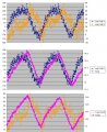
Clearly, the temperature curve shows up on both load cells, though the response seems to have timing delays in call cases...The middle graph (load cell A vs temp sensor) seems to have the most stable curve, though as expected, the load cell is responding to temperature changes quicker than the temp sensor is....Interestingly enough though, load cell B seems to be responding slower than the temp sensor (and much slower than load cell A)....I suspect the way it's mounted is causing a thermal imblance on load cell B....I'm going to change the mounting around some and retest to confirm.
As far as the smoothness of the curves, it seems to me that the temperature sensor may be the better variable to calibrate against, but there would certainly need to be some form of insulation added to slow the rate change. Considering that we're dealing with about 2 grams of variation per degree F of temperature change, that could be quite significant when there's a rapid drop in temp where the load cell could cool several degrees before the temp sensor catches up. Perhaps rate of temperature change could also be included in the calibration equation (ie. a coefficient of how much faster the load cell cools than the air)...Could be something like "X grams per degree + 20 second temp change * some value"....In that case, if the temp is holding steady, it's a standard linear offset. If the air is cooling/warming, also compensate for how much faster the load cell should be cooling/warming. Or some form of regression equation that uses temp and temp change rate both as variables.
On the other hand, if changing the mounting scheme can more align the change between 2 load cells, then that may be the better option, even if the data is more noisy/curve isn't as smooth. Will experiment with both to see what works best.
Load cell A is my primary load cell that weighs my rain, graphed in blue....I connected a secondary "dummy load cell" to channel B (we'll call it "load cell B") right next to it graphed in orange. I also have the SHT31 temperature sensor next to them graphed in pink..I zeroed both load cells and the displayed values are "net drift from the zero point"...For reference, 1 gram is roughly 200 raw values for load cell A and it uses a 128 gain...Channel B only offers a 28 gain, so it's value range is more limited. Temp sensor is logging degrees F to the nearest 2 decimals. Of course, X axis is time and dual Y axis set to best fit the range of variable. I let it data log through a few air conditioner cycles which allowed nearly 1 degree of temperature variations.
Clearly, the temperature curve shows up on both load cells, though the response seems to have timing delays in call cases...The middle graph (load cell A vs temp sensor) seems to have the most stable curve, though as expected, the load cell is responding to temperature changes quicker than the temp sensor is....Interestingly enough though, load cell B seems to be responding slower than the temp sensor (and much slower than load cell A)....I suspect the way it's mounted is causing a thermal imblance on load cell B....I'm going to change the mounting around some and retest to confirm.
As far as the smoothness of the curves, it seems to me that the temperature sensor may be the better variable to calibrate against, but there would certainly need to be some form of insulation added to slow the rate change. Considering that we're dealing with about 2 grams of variation per degree F of temperature change, that could be quite significant when there's a rapid drop in temp where the load cell could cool several degrees before the temp sensor catches up. Perhaps rate of temperature change could also be included in the calibration equation (ie. a coefficient of how much faster the load cell cools than the air)...Could be something like "X grams per degree + 20 second temp change * some value"....In that case, if the temp is holding steady, it's a standard linear offset. If the air is cooling/warming, also compensate for how much faster the load cell should be cooling/warming. Or some form of regression equation that uses temp and temp change rate both as variables.
On the other hand, if changing the mounting scheme can more align the change between 2 load cells, then that may be the better option, even if the data is more noisy/curve isn't as smooth. Will experiment with both to see what works best.




