Facebook
 Google
 GitHub
 Linkedin
DickCappels
- Joined Aug 21, 2008
- 10,661
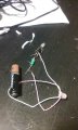
Yes, that is what produces the 180° phase shift that causes the collector signal to become positive feedback to the base.Well, the paper clip was based on the assumption that all that is needed was a center around which wires can be wound. There are even videos of people with inductors called ``air toroid'', and it worked, but read that it would require more turns than ferrite toroid.
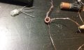
I think the phase inversion you are referring is the direction each pair of wire is going right?
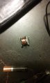
Do you think it's not working because I am using a nut as a toroid, wiring issues, or faulty transistor?
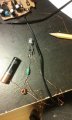
The problem with using steel in these oscillators is that it makes for very low quality inductors at the high frequencies at which the oscillators operate. Two possible solutions are to greatly increase the number of turns so that the oscillator will run at a lower frequency, and sometimes you can get around the problem by boosting the high frequency feedback with a small capacitor across the resistor, and in the photo below.


") .
.