Making a joule thief

Thread Starter

Jose Heredia92

Joined Dec 8, 2017
14
Hello,
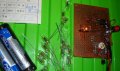
I got interested in making a joule thief, but I want to know if I am doing things right. I'm wondering if this transistor is okay for this project.
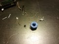
The picture has a small transistor with the numbers 431T6313 and to the left of the transistor is an attempt to make a toroid using an iron bolt with two copper wire coils and blue tape between the coils to prevent the two coils from touching.
Is there any advice you can give me?
 

Attachments

Alec_t

Joined Sep 17, 2013
15,118
Welcome to AAC!
Did you use magnet (enamelled) wire to wind the coils? It looks like ordinary tinned copper wire, which could result in shorted turns.
 

Jose2992

Joined Dec 9, 2017
7
I used a bare wire. Do you think that transistor on the picture is ok for a joule thief? What about the iron nut?

What type of transistor is that? I got it from a cheap battery charger from radioshack.
 
Last edited by a moderator:

bertus

Joined Apr 5, 2008
22,923
Hello,

Are you sure the 431T6313 is a transistor?
Or could it be the TL431 voltage reference?

Bertus

PS it looks like you have two accounts.
We do not allow that over here.
 

Attachments

takao21203

Joined Apr 28, 2012
3,702
a bit on the creepy side this circuit, it is.

Few people use bare wire to make a coil, you can not get enough turns
Also iron is not good tough Ive seen some joule thief with iron core. You need 50 turns or more.
Finally you need a resistor too.

Better get some small electronic parts + some ferrite core or at least wire with isolation

if you dont know the transistor you may have to swap it around until it works (or not)

Theres parts lots to make such circuits on ebay (admitting I sell these).

Also tin foil is not good to connect parts or wires, it may work firstly but soon will fail, will not be relieable, otherwise, guess,
everybody would use tin foils to connect wires.
 

Jose2992

Joined Dec 9, 2017
7
How do I know which one is the collector, base, and emitter in the transistor that I showed? Is there a way to figure it out with a multimeter?
 

philba

Joined Aug 17, 2017
959
You should get some parts that you know what they are - the transistor in particular. Get one with a known part number so you can look at the datasheet and ID the pinout. Use insulated wire for the coil. If there are construction sites near you, there may be cat 5 wire scrapped out. Maybe a kindly electrician will give you some scrap. I've used the individual wires for coils - a couple of meters should be enough. The best coil form is a traditional ferrite toroid but I've seen JTs made with windings on nails so it's not super critical. You can often find toroid coils in broken/tossed electronics - look in the power supplies. You might even be able to add the secondary coil to one. Dumpster diving can yield a lot of good stuff.
 

Jose2992

Joined Dec 9, 2017
7
I did some transistor tests regarding transistor polarity. Looking at the transistor from the flat side, I set the multimeter to diode function, and I got a value when the positive lead was connected to the leftmost pin and the negative lead to the rightmost pin. I did a resistance test by putting the positive lead in the middle (base) and the negative on either of the two adjacent pins. I got 793 Ohms for the left and 672 Ohms on the right. What can you conclude about those measurements?
 

DickCappels

Joined Aug 21, 2008
10,661
From the website referenced in post #10:
"The one with the higher voltage drop will correspond with the emitter of the transistor."
That doesn't always work, but correlates well with my memories of the days when we matched power transistors. If the above is true, the you have an NPN in which the one on the left (793 ohms) is the emitter and the one on the right (672 ohms) is the collector.

Here is a nice point: Since the highest voltage in this circuit are going to be under 5 volts you can operate the transistor with the emitter and collector swapped without hurting it (unless it happens to be an exotic (expensive) RF transistor, which is very unlikely. It might even work well when in "backwards". You can merely swap the emitter and collector connections to see which arrangement gives you the brightest light.
 

Jose2992

Joined Dec 9, 2017
7
Also, how do I measure the voltage produced by the joule thief? I put the negative lead of the MM to the negative terminal of a 1.20 v battery and the positive lead to one of the pins of the transistor and I only get 0.8 volts. I am using a iron core, insulated wire, npn transistor.
 

philba

Joined Aug 17, 2017
959
Without an Oscilloscope, it will be hard to tell. You could try the AC setting of your DMM but who knows if it will be accurate. This is a representative example.
 

DickCappels

Joined Aug 21, 2008
10,661
The DC difference between the battery and the LED is nearly zero because the inductor is nearly a dead short at DC, which is that you DVM measures.

If you add a diode and capacitor you can make the output DC andmaybe even make the LED brighter in the process. You can then measure the output accurately with a DVM.

upload_2017-12-15_7-16-27.png
Keep in mind that this circuit produces a nearly constant current so the voltage you measure will be a function of the current out of the inverter and the IV curve of the LED (different for each LED).

upload_2017-12-15_7-18-33.png
 

DickCappels

Joined Aug 21, 2008
10,661
I do not think so. (I think this will not mean anything to you initially but you are missing a phase inversion -either a center-tapped inductor or some arrangement that is much more exotic. The paper clip makes me wonder where you got that and whether you are serious about this.
 

Thread Starter

Jose Heredia92

Joined Dec 8, 2017
14
Well, the paper clip was based on the assumption that all that is needed was a center around which wires can be wound. There are even videos of people with inductors called ``air toroid'', and it worked, but read that it would require more turns than ferrite toroid.

I think the phase inversion you are referring is the direction each pair of wire is going right?
Do you think it's not working because I am using a nut as a toroid, wiring issues, or faulty transistor?
 
Top