Facebook
 Google
 GitHub
 Linkedin
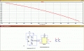
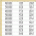
I want to show Vout-R5 graphics.R5 is a variable resistor that changes its resistance between 300 ohm and 700 ohm.I want to add R5 to x-axis and Vout y axis.Can you help me ?I don't know the LTspice so good.I added the screen shot and test file
Attachments
-
 18.9 KB Views: 14
 -
1.7 KB Views: 4