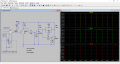
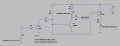
Yes...to ensure the transistor is completely off.This is interesting. What are the 47k resistors going to ground used for? Maybe to clean up any residual current from the base of the transistors?
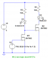
I tried this design out and it works as expected. The fault signal line still drops but not as much. it measured 2.0V at .28ma while the green light was lit. It is certainly not capable of sourcing much current.Here is a variant of Alex_T's circuit.
It important that the monitor circuit use an external 5v power source and not use power from the fault pin to power the circuit.
It sounds like the fault signal has very limited power.
Hmmm...280uA current draw is pretty small and I wouldn't expect that to load down a 5v signal much, if at all.I tried this design out and it works as expected. The fault signal line still drops but not as much. it measured 2.0V at .28ma while the green light was lit. It is certainly not capable of sourcing much current.
Sorry eetech, I meant 280ma not .280ma.Hmmm...280uA current draw is pretty small and I wouldn't expect that to load down a 5v signal much, if at all.
I'm starting to think there's something wrong with the fault output signal.
Sorry eetech, I meant 280ma not .280ma.
Yes I have many of these drives in service and one on my test bench hooked to a motor/encoder for testing this circuit. I have a pushbutton set up that will short the encoder's +5V to the fault signal and that does reset the error. The drive has small LED'S on it that show the fault status. Everything is working as it should, I was just concerned about the the fault signal dropping to about +2V when enabled (green led on) if that would cause any issues when the drive is pushing a heavy load. I would also like to send this signal to the input of the machine's breakout board (PMDX-424) so the software will recognize the fault and halt the program. I am not sure yet how much current the input will need and how it may affect this circuit.[/QUOT
280mA current draw out of the fault signal pin is a lot of current.
If you have an external supply for the monitoring circuit, there shouldn't be that much current draw from the fault pin. Should only draw about 1ma (actually about 915uA) when the monitoring circuit transistor is on. Have to figure out why the fault signal drops to 2v when the monitor is connected.
Is there something else connected to the fault pin?
What is the power supply voltage to the GX320? Is the power supply going in to current limit?
Do you happen to have a schematic of the GX320 fault I/O circuit?
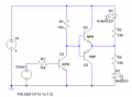
Thanks for all the options. So a mosfet requires much less current to the gate than your typical BJT needs to the base correct?..... yet another variant; this time using a BJT buffer driving a push-pull pair of BJTs
View attachment 104748
Correct. Current is drawn only very briefly to charge or discharge the gate capacitance.So a mosfet requires much less current to the gate than your typical BJT needs to the base correct?
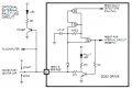
That's a OC drive, with an embedded current limiting resistor.The only thing I could find for the drive's fault circuit is actually from the older "G320" model
Here is the modified schematic.Disconnect the monitor, then try taking a 2907 (I think you have one) and connect it like the one in the schematic you posted.
except:
1. Replace the 220 ohm resistor and LED with a 4.7k resistor.
3. Connect the base of the monitor circuit to the junction of the 2907 emitter and resistor.
See if that works
What does OC stand for?That's a OC drive
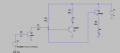
This circuit worked well. The Fault signal voltage only dropped to +4.68 volts from +5I sketched it up here.
R1/R5/Q3 is internal to your device.
R2 is the pull-up resistor - its value doesn't matter as long as it is reasonably high;
When Q3's collector goes low, D1 lights up; When Q3's collector goes high, D2 lights up.

--My Signal Code Starts Here
--Code added to the "Screen Load Script"
SigLib = {
[mc.ISIG_INPUT1] = function(state)
local inst = mc.mcGetInstance()
local input_1 = mc.mcSignalGetHandle(inst, mc.ISIG_INPUT1) -- Get handle for input 1
local input_1_state = mc.mcSignalGetState(input_1) --Get state of drive fault signal
if (input_1_state == 1) then -- Check to see if fault signal is on
mc.mcCntlEnable(inst,false) -- Disable drive
wx.wxMessageBox("Z Axis Drive Fault Triggered E-Stop") -- user message
else
wx.wxMessageBox("Z Axis Drive Fault Cleared")-- user message
end
end
}
--My Signal Code Ends Here