Pi-Matching Network Simulation in LTSPICE

Thread Starter

ssgill2

Joined Feb 13, 2017
4
Hello All,

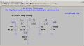
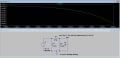
Just joined this forum after finding it very useful for other questions I had. I am currently working on a simple project which involves designing a pi-matching circuit for a source resistance of 50 ohms and load resistance of 800 ohms. The frequency of operation (center frequency) given to me is 800 MHz and bandwidth specification given to me is 25 MHz. From this information, I calculated my required Q factor and designed my pi-matching networks. I have used the block DC format.

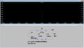
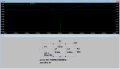
Using the .net and .ac commands, I simulated my S11 parameter to ensure it is less than -10 dB as that means good matching. The question is how do I interpret the S11 simulation? It just lines going up and down to me. In the attached file, I included the S11 plot and my schematic. My S11 is in the mdB range so I assume I have designed a good matching circuit?

Thanks for reading
Simardeep Gill
 

Attachments

ChrisTheEE

Joined Feb 23, 2017
5
Hi Simardeep,

For starters, your load resistor is set to 50 Ω and your simulation only runs from 200 MHz to 400 MHz. Set your load resistor to the 800 Ω you specify in your post. If you're looking at 800 MHz with a bandwidth of 25 MHz, then you'll want to look at a range centered around 800 MHz. 787.5-812.5 MHz at a minimum, since that's your band of interest, but it's always informative to look beyond that.

I've made these changes and run the simulation from 700-900 MHz. S-parameters are fantastic, but that's an entirely separate post. For this simulation, S11 tells you how much of your input signal gets reflected back to the input (solid line) and at what phase (dashed line). Ignore the dashed line for now.

If the signal is being reflected, it isn't being transmitted. Based on your post, you want the S11 measurement to be at least -10 dB from 787.5 to 812.5 MHz. The lower the reflected signal, the more power being delivered to your load. For some people, it seems kind of backwards to look at that, when you could also look at S21 and see what's being transmitted from the source to the load, but that's how RF guys roll.

So, back to S11. Assuming an input of 0 dBm (1 mW), a reflection magnitude of -10 dB at a given frequency means that only -10 dBm (0.1 mW) is reflected back to the source, which means 0.9 mW (or 90% of the input) was delivered to the load. If S11 is -20 dB, then 0.99 mW is delivered to the load.

With that being said, I don't think your network quite gets you there. See the second screenshot. Also, you might want to change your simulation settings. If you change to linear with 401 points and 700-900 MHz, you'll get 500 kHz steps so you can stick a cursor right where you need to measure.


Hope this helps!
Chris
 

Attachments

Last edited:

Thread Starter

ssgill2

Joined Feb 13, 2017
4
Hi ChrisTheEE;

Yes, I realized the range of interest and the load resistor value should be adjusted after and I have got it work. Your explanation of the s-parameters really helped. I was always accustomed to the mathematics of them and seeing the simulations now with your explanation helped.

Thank you!
 

377Ohms

Joined Sep 9, 2015
10
Hello Simardeep,

I'm not sure about the circuit you posted, but I'll try to attach two ways of getting S-Parameters in LT-Spice that seem to work OK. (I'm not sure this Forum will allow me to attach anything yet as I'm a new poster here.)

Please pay attention to the References in the headers on the schematic sheets for the simulations, especially the link to the ee.sun.ac.za domain in the T-Pad example (ee.sun.ac.za is the EE Department at Stellenbosch University in S. Africa).

Note, I believe there is an error in the Stellenbosch LT-Spice write-up. Their input source is AC 1V, I think this is wrong. When your source and load impedances are the same (e.g. both 50 Ohms) the source amplitude should be 2V, not 1V. This is proven in my included simulation for the T-Pad attenuator where you can see the [in] Net Label plot is 0dB and the [out] plot (or S21) is -6dB exactly with the source at 2V (+6dB), not 1V (0dB).

Have Fun, David in Jakarta
 

Attachments

377Ohms

Joined Sep 9, 2015
10
Hello again... A few more things:

1. In my attached file:

S-Parm_Built-In_T-Pad_v101a.asc

You can learn all about the LTspice schematic Dot Command:

.net I(Rload) Vsrc

By reading the LTspice Help here:

Help > Help Topics > LTspice > Dot Commands > .NET -- Compute Network Parameters in a .AC Analysis

In the Help text there are instructions on how to use the example files included with LTspice called S-param.asc & S-param.plt to see how to use this .NET directive.

I attach a .txt file of the Help section text.
I also attach a .zip of the LTspice included example files S-param.asc & S-param.plt

2. I attach the .pdf file that is available for the public to download from Stellenbosch University at:

http://courses.ee.sun.ac.za/HFTegniek_414/JB/notas/Two port parameters in LTSPICE.pdf

3. Note, while I still believe the use of the source AC 1V is incorrect in the Stellenbosch example (it should be AC 2V), it is possible to use AC 1V in some examples where the .NET directive is employed. This can be seen in the LTspice included example files S-param.asc & S-param.plt referenced above.

I hope this helps... David
 

Attachments

Thread Starter

ssgill2

Joined Feb 13, 2017
4
Thank you very much David, your information is helping me very much in my new project: Wide-Band Amplifier.
 
Top