 Facebook
 Google
 GitHub
 Linkedin
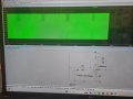
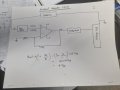
I built the function generator circuit on a breadboard. I applied a signal with an amplitude of 1.06Vpp and a frequency of 5MHz using the DDS 9851 and then sent it to the operational amplifier, AD 8001. After amplification, the signal increased to 4Vpp while maintaining the same 5MHz frequency. However, some distortion appeared in the signal after amplification. To address this, I connected a ferrite bead with a rating of 1kΩ in series with the signal. After using the ferrite bead, the signal became much cleaner with very little noise. This allowed me to remove the large laboratory function generator and apply the amplified signal directly to my sensor.
This is my first experience working with LTSpice software. I recreated the same circuit in LTSpice, using the same resistor values and one simulation with more resistors value. However, in the simulation, the signal amplitude did not increase as it did in my real circuit. The signal did not amplify after using the same operational amplifier in LTSpice. Do you think LTSpice should amplify the signal as much as the real circuit does when using a single operational amplifier?
I have drawn a picture of my real circuit, which I will show to you along with the LTSpice circuit and its results. Additionally, I will show you the signal results that I measured with an oscilloscope. Could anyone please share your experience and tell me whether this significant difference in signal amplitude between the real circuit and the LTSpice simulation is common when using simulation software? Or could this discrepancy be due to a mistake on my part, given that there are differences between reality and software simulations? I f there is some mistake on my side, can someone highlight my mistake please
Attachments
-
 186.3 KB Views: 27
 -
 125.7 KB Views: 27


