Facebook
 Google
 GitHub
 Linkedin
I just started learning circuit design. I can't claim to be good at this. There are some parts in the circuit that I need to change and I couldn't get over it. I need your help. I really want to learn how it's done.
75v dc should enter the vin (input of my integrated circuit). I had to calculate the required ac voltage and use it as a power supply(ı calculated 53v AC). I should also get 5v at the output of my circuit. IC model , LT3758. No matter what I do, everything seems totally wrong. I need your advice.
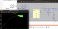
Wherever I want to display the voltage,I see wavy forms
75v dc should enter the vin (input of my integrated circuit). I had to calculate the required ac voltage and use it as a power supply(ı calculated 53v AC). I should also get 5v at the output of my circuit. IC model , LT3758. No matter what I do, everything seems totally wrong. I need your advice.
Wherever I want to display the voltage,I see wavy forms
Attachments
-
4.7 KB Views: 10