LT3511 Isolated Flyback Converter

Thread Starter

aiaie

Joined Apr 30, 2025
4
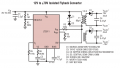
I've built the ±70V isolated flyback converter circuit using the LT3511 IC, based on the application example provided in its datasheet. My goal is to use this power supply to drive a voltage-to-current converter that needs to source up to 2 mA into loads as high as 30 kΩ.

When I test the converter without any load, I only get about ±40V at the output. When I add a load, the voltage drops even further. I’m not sure what’s going wrong.

I simulated the circuit in LTspice, and it performs as expected. The measured voltages on the actual IC pins also closely match those in the simulation, so I’m having trouble pinpointing the issue.

How should I go about troubleshooting this? What could cause this kind of voltage drop, and how can I ensure that I get a stable ±70V output across the expected range of load conditions?
Flyback_Troubleshoot.PNG
 

ericgibbs

Joined Jan 29, 2010
21,391
Hi aiaie,
Welcome to AAC.
Please post your LTSpice asc file, we can then compare results on the simulation.
E
Also any LTS models you may use.
 

MisterBill2

Joined Jan 23, 2018
27,184
If the simulation works but the actual assembled circuit does not deliver the same results, then obviously SOMETHING IS DIFFERENT!! The very first thing I would check is the impedance of the power source. By that I mean the power supply's ability to deliver the required current, which is in pulses for a fly-back circuit. The next thing to check is that transformer that trades current pulses for voltage pulses. IF it does not have enough iron to store enough magnetic energy to produce the voltage and current specified then that will be the flaw.
 

Thread Starter

aiaie

Joined Apr 30, 2025
4
If the simulation works but the actual assembled circuit does not deliver the same results, then obviously SOMETHING IS DIFFERENT!! The very first thing I would check is the impedance of the power source. By that I mean the power supply's ability to deliver the required current, which is in pulses for a fly-back circuit. The next thing to check is that transformer that trades current pulses for voltage pulses. IF it does not have enough iron to store enough magnetic energy to produce the voltage and current specified then that will be the flaw.
The circuit design, including transformer, is taken from the datasheet, so I’m assuming it’s generally appropriate for this application. Regarding the power supply, I’m using a 30 V / 5 A source, and the flyback converter is expected to output 4 mA at 70 V.
 

MisterBill2

Joined Jan 23, 2018
27,184
I would suspect that perhaps the zener diode is not right, if everything else is exactly correct. AND STILL, there could be a connection with excess resistance. That has been a source of problems for several folks in the past.
In all switching regulator circuits, every connection is important.
 
Top