Facebook
 Google
 GitHub
 Linkedin
Hi all,
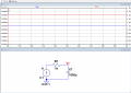
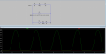
I am simulating a circuit on LT Spice, and using a diode to restrict the flow of current in the opposite direction. The diode is restricting the current to flow in the negative direction but they are increasing the voltage by a lot. I'm using a 10V voltage source and when it passes the diode it's peak reaches approximately 700V. I am attaching screenshot of the schematic and the waveform here.
Thank you
Attachments
-
 36.6 KB Views: 27