 Facebook
 Google
 GitHub
 Linkedin
I am a regular designer of digital circuits, MCU projects etc, but totally new to LT Spice.
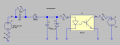
I have tried to follow some introductory articles but am still floundering somewhat. I am trying to analyse a fairly simple circuit, designed to take input from a 230V nominal supply and cause an opto-isolator to trigger an input on an MCU. I have attached the circuit diagram that I have put into LT Spice below.
My problem is that I cannot see how to set up the voltage source/analysis parameters in order to simply see what voltages etc I am getting in various parts of the circuit. I know that there are people on this forum that eat LT Spice for breakfast! Can you advise, please?


 speculative aproximation


