Facebook
 Google
 GitHub
 Linkedin
Hi everybody!!
I am having confusing regarding of the LR low pass filter.
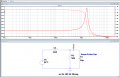
Base on my simulation on the LTspice, i am seeing that the output voltage starts attenuating at about 2MHz. (attachment 1)
However, on my actual experience, i am seeing Vout starts increasing when Frequency is at about 391KHz (scope 2), you can see Channel 2 voltage is slightly greater than channel 1 voltage, and Vout keeps increasing (max voltage = 24V) until frequency is about 1MHz, then Vout start decreasing.
It seems to me it can behave like a band pass filter, but some how the Vout is able to climp up linearly proportional with frequency.
I am curious the reason causing the voltage increase. How reality does the inductor behave in this circuit?
Channel1: input from Signal generator (5Vac)
Channel2: Output at resistor
Please advice to help me understand!!
Thank you
I am having confusing regarding of the LR low pass filter.
Base on my simulation on the LTspice, i am seeing that the output voltage starts attenuating at about 2MHz. (attachment 1)
However, on my actual experience, i am seeing Vout starts increasing when Frequency is at about 391KHz (scope 2), you can see Channel 2 voltage is slightly greater than channel 1 voltage, and Vout keeps increasing (max voltage = 24V) until frequency is about 1MHz, then Vout start decreasing.
It seems to me it can behave like a band pass filter, but some how the Vout is able to climp up linearly proportional with frequency.
I am curious the reason causing the voltage increase. How reality does the inductor behave in this circuit?
Channel1: input from Signal generator (5Vac)
Channel2: Output at resistor
Please advice to help me understand!!
Thank you
Attachments
-
 29.4 KB Views: 8
 -
 180.1 KB Views: 8
 -
 170.4 KB Views: 8
 -
 977.4 KB Views: 6