Facebook
 Google
 GitHub
 Linkedin

The input to the circuit is the open collector output from another device. I want to understand the time constant raise and fall time and also the cutoff frequency. I do not know much on the open collector when i read it says it can only pull the line low and it cannot pull the line high and need pull up resistor. Analysing the actual circuit
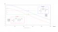
If initially the line is at 3.3V for it to go to Low the time constant will be R2 * C1 = 4.7K * 8.2nF = 38.54uSec.
Again when the open collector output is floating the time for it to go high is tau = 38.54uSec.
The signals beyond the frequency = 1/(2*pi*R2*C1) =4.12Khz.

As usual i am confused of whether to use R1 or R2 for Tau calculations, or both?


")