Facebook
 Google
 GitHub
 Linkedin
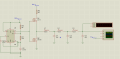
Hi all,i design a Low Pass Filter and to prevent the low power,it is LC network.My low pass gives the perfect sin wave but on the board,it loses the amplitude. How can i solve this porblem.thanks for helping,the low pass is attached at below.
.
.
")