low_voltage cut off for solar usb charger

Gaudeamos

Joined Jun 24, 2013
16
Does the USB specification deal with this? I mean, if every device the OP might charge with his device will be smart and disconnect itself when it sees low voltage on the USB host, maybe the OP doesn't need a low-voltage shutoff at all.
I don't think so. I'm aware of a tolerance (+/- 0.25V I think), as well as a requirement for a host to be able to source 100-500mA as negotiated. To my understanding that negotiation is seldom implemented.

From what I've seen of USB power interfaces as implemented on DIY-type projects (eg a portable power pack), the 5V is supplied from batteries using a DC-DC boost converter. So I guess that the 5V would be maintained for an open-circuit USB output, but that would sag pretty quickly as current is drawn when the host's batteries run low. In this case the host would be responsible for a reliable shut-down to protect it's own batteries from damaging deep discharge, not necessarily for the benefit of the connected client device.

This self-preserving issue aside (it doesn't apply to solar batteries), I gotta assume that undervoltage supply conditions happen all the time in the USB world (like, USB wall warts rated at 200 mA never get overloaded?...). I can imagine some client device sucking in whatever little power is offered by a host via DC-DC boost conversion. If I had to recharge my batteries from such a host, that's what I would do. From that point of view, I would leave it up to the client device how to react to undervoltage conditions.
 

Thread Starter

Elokuu

Joined Aug 29, 2012
26
Hey,

First of all thanks for the replies and sorry for the late reply. But I have been at a festival over the weekend, so I just came back today and could start experimenting.

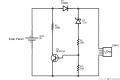
First I tried the shunt regulator as suggested by Wayneh and I couldn't get it to work at all. I probably understood something wrong. I built it as followed: (see attachment No.1). The phone didn't showed the "charging sign" till I covered half of the panel so it supplies around 5V. Then the phone showed it is charging but it didn't drain any current :confused:. Maybe somebody has an idea what I did wrong?
So I switched back to my first 7805 regulator approach (without any low voltage shut off) and tried it out. Instead of a Solar Panel I first connected it to some variable wall wart to measure a little bit around. The value were quite unstable so this was the average:

Input (from wall wart) Output (at USB Connector)
6,5V --> 5,05V / 0mA
7,2V --> 4,95V / 90mA +- 10mA
8,5V --> 4,95V / 160mA +- 10mA
10,3V --> 4,95V / 170mA +- 10mA
11,9V --> 4,95V / 170mA +- 10mA

When I connect my phone to the USB port of my PC or to my USB wall charger it charges with 330mA. Why does it charge with a much lower current with "my curcuit"? The wall wart was rated with 500mA.


Then I connected the solar panel and the measurements were pretty weird and unstable. The phone showed all the time the "charging sign", but often it didn't drain any current. I guess if the current or voltage is to low it just stops charging, even so it shows still it is charging. The same happened when I dropped the voltage from the wall wart to under 6,5V. The phone still showed it's charging but it didn't draw any current.

However I think that exactly happened what Gaudeamos was expecting. The phone stopped charging when the voltage was to low and then the circuit was recovering, the voltage raised and started the charging process again. So the voltage was to low again and it stopped charging, aso. So it was kind of oscillating.


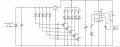
Also my bargraph seems to be quite useless, because I never now when the phone is actually charging and when not. So I don't know if the bargraph shows the voltage with the load connected or not :(. Does anybody has an idea how I can make an indicator LED which shows when the device is actually drawing current? Apparently I can't count on the phone "charging sign".
 

Attachments

LDC3

Joined Apr 27, 2013
924
Also my bargraph seems to be quite useless, because I never now when the phone is actually charging and when not. So I don't know if the bargraph shows the voltage with the load connected or not :(. Does anybody has an idea how I can make an indicator LED which shows when the device is actually drawing current? Apparently I can't count on the phone "charging sign".
You could probably still use the bar graph, but the conditions need to change. Since you want to measure when the phone is charging, then you need to measure the current into the USB port. Put a small resistor in series with the port and connect both ends to a high impedance op-amp (preferably with FET inputs). With a high enough gain, you will be able to monitor the current.
 

wayneh

Joined Sep 9, 2010
18,133
Your current dump arrangement won't do anything until the USB voltage exceeds 6.4V, a bit high I think. The attached device may have shut off charging to avoid damage. The transistor will start to conduct when its base is ~0.65V. With your divider, the voltage after the zener will be 1.3V at that point, and thus 6.4V at the USB.

For a charge indicator, use a low ohms resistor (maybe 0.1Ω) and a comparator to watch the voltage drop across it.
 

Thread Starter

Elokuu

Joined Aug 29, 2012
26
Your current dump arrangement won't do anything until the USB voltage exceeds 6.4V, a bit high I think. The attached device may have shut off charging to avoid damage. The transistor will start to conduct when its base is ~0.65V. With your divider, the voltage after the zener will be 1.3V at that point, and thus 6.4V at the USB.
But I also tried removing R3, so the transistor conduct at ~5.7V and still nothing happened. When I measure the voltage at the USB-port it is always just ~0.7V (the blocking diode voltage drop) lower then at the solar panel. Will the voltage first drop to ~5.7V when the phone starts charging (a load is connected) or should it also drop to ~5.7V without any load connected? Unfortunately I don't have any smaller zener diode then 5.1V at the moment. And I have to "finish" (as good as it gets) the solar charger till tomorrow, because then I'll hit the road again for two month and I'm planing to take the charger :rolleyes:.

For a charge indicator, use a low ohms resistor (maybe 0.1Ω) and a comparator to watch the voltage drop across it.
I have never worked with op-amps before, but I read a little about it yesterday. And as I understand it now, it would compare the voltage before and after the resistor. When there is current flowing, there is a voltage drop and the output will get high because V+ and V- are different. When there is now current, then there is no voltage drop, so V+ and V- will be equal and the output will be low. Did I understand it more or less right?

So the schematic would be like this: (see attachment)

The only op-amp I currently have is the LF356N. Would this one be fine? The schematic shows the LM358, but this is just because Fritzing doesn't have the LF356N in the library.

Thanks again
 

Attachments

LDC3

Joined Apr 27, 2013
924
So the schematic would be like this: (see attachment)

The only op-amp I currently have is the LF356N. Would this one be fine? The schematic shows the LM358, but this is just because Fritzing doesn't have the LF356N in the library.
You want the 2 leads reversed because when the + input is higher than the - input, there is a positive voltage on the output. When the inputs are equal, the output is 0V.
 

wayneh

Joined Sep 9, 2010
18,133
In my experience it's easier to compare the voltage on the load end of the shunt resistor to an adjustable reference voltage so that you can tweak it to switch just exactly where you want it. The comparator will have some internal offset and that can cause confusing behavior if you cannot adjust it away.

All this means is that you may need a couple resistors to tweak (divide up or down) the voltage you read from the supply end of the shunt resistor. If the offset works in your favor, you won't need these, but Murphy's law doesn't usually work that way.

You can choose to put the shunt on the positive or negative leg. The choice may depend on your op-amp - you need to be sure the op-amp or comparator includes one of the power rails in its common mode voltage range.

It appears the LF356 can sense to the positive rail, so you'll want to put the shunt on the high side.
 

Thread Starter

Elokuu

Joined Aug 29, 2012
26
All this means is that you may need a couple resistors to tweak (divide up or down) the voltage you read from the supply end of the shunt resistor. If the offset works in your favor, you won't need these, but Murphy's law doesn't usually work that way.
like this: (see attachment)

You can choose to put the shunt on the positive or negative leg.
Does this mean if I put the shunt resistor before or after the load?

Thanks for the replies and sorry for all my questions. I'm pretty new to all this stuff :(
 

Attachments

wayneh

Joined Sep 9, 2010
18,133
Does this mean if I put the shunt resistor before or after the load?
Yes, and I think you've got it right. Once you know what voltage you need on the reference pin, you may want to replace the variable resistor with fixed values. Just an option.
 
Last edited:

wayneh

Joined Sep 9, 2010
18,133
Will the voltage first drop to ~5.7V when the phone starts charging (a load is connected) or should it also drop to ~5.7V without any load connected?
That current dumping arrangement will keep the voltage from going over 5.7V at the USB port whether the load is connected or not.
 

Thread Starter

Elokuu

Joined Aug 29, 2012
26
Hmmm. I built a test circuit to see if I understood the working principle of the op-amp and it worked. I was so happy, so I wanted to try it at the actual solar circuit.

But as soon as I add a shunt resistor in series with the USB-port the phone stops charging, or it just draws 5mA :mad:. I used a 5ohm resistor as it was the smallest I had. I didn't even add the op-amp, I just added the 5ohm resistor in series with the USB-port and it stops charging. Any idea why?

Thanks
 

LDC3

Joined Apr 27, 2013
924
It is probably because the 5Ω resistor causes too much of a voltage drop. The phone thinks that the USB is overloaded with other devices since it detects a voltage below some threshold, so it won't draw the current it needs to charge the batteries.
 

Thread Starter

Elokuu

Joined Aug 29, 2012
26
That current dumping arrangement will keep the voltage from going over 5.7V at the USB port whether the load is connected or not.
Unfortunately it doesn't :(, at least not with the circuit I posted. The voltage at the usb-port is just 0.7V lower then the voltage from the solar panel. The transistor is fully saturated. Maybe my resistor/diode/transitor values are wrong :confused:?
 

Thread Starter

Elokuu

Joined Aug 29, 2012
26
It is probably because the 5Ω resistor causes too much of a voltage drop. The phone thinks that the USB is overloaded with other devices since it detects a voltage below some threshold, so it won't draw the current it needs to charge the batteries.
I thought the same, but the voltage drop is actually pretty small. It drops from 5.08V to 5.02V, so it should still be fine, because when I connect it to the solar panel it keeps on charging till the voltage drops below 4.3V.
 

Gaudeamos

Joined Jun 24, 2013
16
Hi Elokuu

I don't have any real experience working with solar panels, but I've spent time reading up on them. So I'll offer some purely academic advice here, but the warning is that I've never played with any of this.

Consider a solar panel to be a weak battery, which is exactly what it is. You might see a useful voltage when there's no load, but as soon as a load draws current the battery's voltage sags. This is the "VI curve" that wayneh and tindel mentioned early in this thread. It sounds like you are attempting to draw enough current to force your cell to the (voltage) bottom of it's VI curve, so that it delivers only 0.7V, below which your circuit gives up trying to draw current.

Ideally, you should be drawing just enough (and not more) current to keep your VxI (power product) at its maximum point along the panel's VI curve, the Maximum Power Point (MPP). Also, keep in mind that your solar panel's VI curve (and consequently the MPP) changes constantly with available sunlight energy. There are specialized switch mode regulators available that manage Maximum Power Point Tracking (google MPPT); I've seen specs for one (from TI as I remember, can't find the datasheet now) that constantly monitors both source and load for optimum power transfer.

Ignoring this ideal, your application requires at least 5V (actually 4.75V per USB spec), so you would need to regulate your panel's current in order to keep the output voltage (at least) to the required minimum. A switch mode buck regulator will work this way (I don't know if they all do, I have no experience in that area either). A linear regulator like 7805 will keep drawing current below its dropout voltage, as you've observed.

Research material:
http://en.wikipedia.org/wiki/Maximum_power_point_tracker
www.ti.com/lit/an/slva446/slva446.pdf

May you be blessed with enough sunshine (and the means to harvest it:cool:) to keep your batteries happy! ;)
 

Gaudeamos

Joined Jun 24, 2013
16
I'm thinking it might be useful to know how a Li-ion battery needs to be charged.

A Li-ion quick charge is a 2-phase cycle consisting of
1. a constant-current phase whereby current is limited to a fraction of the mA-hr battery capacity (typically around 1000 mA-hr for phone batteries, I'm guessing it's close to what a wall-wart charger can provide); this phase terminates when the battery's voltage reaches 4.2V ...
2. a constant-voltage phase whereby the voltage is limited to 4.2V while the battery continues to charge; this phase terminates when the current has decayed to a specific fraction of the battery's mA-hr capacity (don't know what that threshold is offhand).

So, given a weak charging source, the phone may never see the charging current it expects during the constant-current phase, during which the battery's voltage should increase from 3V (a discharged battery) to 4.2V. It may give up at that point. If the charger manages to make it to phase 2, a weak source current would be interpreted as the end-of-charge condition...
 
Last edited:
Top