Logic gate help?

JohnInTX

Joined Jun 26, 2012
4,787
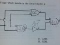
Have you done the truth table for the 2 inputs?


00 -> The output of the OR gate will be 0 making the output through the AND=0

01/10 The output of the OR gate = 1, the output through the AND = 1
(00,01,10 on the parallel AND->NOT makes the other input 1. 1&1=1

11 -> the output of the OR is still 1 but the NAND (AND->NOT) is now 0. The 0 on the other input of the output AND makes the output of the circuit 0.

The truth table is:
00 - 0
01 - 1
10 - 1
11 - 0

Looks like an OR except for the 11 input condition so.... exclusive OR.
 

Thread Starter

pfelectronicstech

Joined Jan 18, 2012
178
Thanks John, I'm just not good with logic gates, and truth tables. Its the area of the program I had most trouble with. For some reason it confused the hell out of me, but I'm trying to really get it.
 

JohnInTX

Joined Jun 26, 2012
4,787
Didn't mean to scold... Hopefully, you understand the logic from input to output for the 4 possible input conditions. It can be confusing but take it step by step.

One cheap way to look at this is to pay attention to the unique input conditions of the AND and OR gates i.e. for AND, look for 11, that's the only condition for a 1 output, for OR, look for 00 for a 0 output. So for your OR - AND input conditions 00 and 11 are the ones to try first as they are the unique output conditions for each gate. After that, any 0 input will change the NAND side and any 1 will change the OR side.

Presumably, you'll get into Boolean algebra to describe and solve this stuff. Having facility with truth tables will help immensely with that.

BTW: The XOR is most useful in arithmetic circuits. If you connect an output to the node between the AND and NOT, you make a half-adder. The original output is 2^0 and the new one is 2^1. 1+1 on the input gives 10 (2 in decimal) out. Fun!

Good luck!
 
Last edited:

DerStrom8

Joined Feb 20, 2011
2,390
What format are you looking to put the output in? Boolean? Truth table? Karnaugh map?

And a shot of the entire problem (including inputs) would help a lot, too.... ;)
 

Thread Starter

pfelectronicstech

Joined Jan 18, 2012
178
Thanks guys, that was the whole question. That circuit, those logic gates, what is the resulting output. This is the only part of the course I just didn't click with.
 

DerStrom8

Joined Feb 20, 2011
2,390
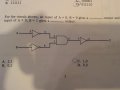
Another challenge, my guess is circled. Any clue will be greatly appreciated.
Okay, let's examine the input of A=0 and B=0 first. Both inputs have NOT gates, so you can immediately invert them. So the inputs to the AND gate are 1 and 1. What happens if both inputs to an AND gate are high? The output is.....? Then you invert that to get Z.

Then do the same thing, but with A=0 and B=1.

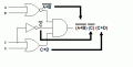
I suggest you copy down the circuit and write the current state on each connection. Like this:

gate4.gif

Don't hesitate to write down the state after each gate. It will help you keep track of what's going on.
 

WBahn

Joined Mar 31, 2012
33,186
What method are you using to get at your choice of the answer? If you could describe your reasoning, it would help us spot where you are going awry.

For the truth tables of the various basic gates, just remember that they geenrally follow what we mean when we use AND and OR in everyday conversation.

Y = A AND B

means that Y is True only if A is True AND B is True. In other words, only if all of the inputs are True. Consider the sentence, "You can go out and play if you do your homework and clean your room." This becomes:

Y = You can go out and play
A = Homework is done
B = Room is clean

What if, instead, the sentence had been, "You can go out and play if you do your homework or clean your room." The same terms above still apply, but now it is

Y = A OR B

And Y is True as if A is True OR B is True In other words, as long as at least one of the inputs is True.

As has been suggested by others, do not hesitate to draw a truth table that walks the signals from input to output step by step. Just label each node and add a column for that node and then work from the inputs to the outputs, filling in each column as soon as the columns associated with all of its inputs nodes are complete.
 

Thread Starter

pfelectronicstech

Joined Jan 18, 2012
178
Okay, let's examine the input of A=0 and B=0 first. Both inputs have NOT gates, so you can immediately invert them. So the inputs to the AND gate are 1 and 1. What happens if both inputs to an AND gate are high? The output is.....? Then you invert that to get Z.

Then do the same thing, but with A=0 and B=1.

I suggest you copy down the circuit and write the current state on each connection. Like this:

View attachment 47714

Don't hesitate to write down the state after each gate. It will help you keep track of what's going on.
Thanks right, NOT gates invert. Makes them pretty easy to understand. So the answer is 1,1.
I feel I may be kinda not making people happy with these question. Its just that for whatever reason this part, Boolean algebra and gates really gave me fits. This is the only part of the program that gave me this much trouble. Not saying I was Einstein with every part, but this part in particular gave me trouble. Truth tables in particular. Thanks for the help, and I apologize if I aggravated anyone.
 

DerStrom8

Joined Feb 20, 2011
2,390
Thanks right, NOT gates invert. Makes them pretty easy to understand. So the answer is 1,1.
I feel I may be kinda not making people happy with these question. Its just that for whatever reason this part, Boolean algebra and gates really gave me fits. This is the only part of the program that gave me this much trouble. Not saying I was Einstein with every part, but this part in particular gave me trouble. Truth tables in particular. Thanks for the help, and I apologize if I aggravated anyone.
I'd suggest you re-check your logic there. Don't forget there's another NOT gate after the AND gate. And that the X,Y answer system means for condition (a) the answer is X, and for condition (b) the answer is Y.
 

Thread Starter

pfelectronicstech

Joined Jan 18, 2012
178
OK, lets get down to business because I want to get this myself and its annoying me. If we start with a 0,0 on the input, then the NOT gates invert both to 1,1, right so far? Where I go wrong is what does the AND gate then do to it?
Thanks for your patience. Is this generally considered the easy stuff, because i feel stupid, it confuses the heck out of me.
 

Thread Starter

pfelectronicstech

Joined Jan 18, 2012
178
Hold it, based on what I see on Wikipedia, the 1,1 when it goes through the AND gate is then 1,1 but then it goes through the NOT gate again which makes the answer 0,0. Did I finally get it! I'm starting to kinda get it.
 

DerStrom8

Joined Feb 20, 2011
2,390
I think you're starting to get the hang of it, yes. An AND gate outputs a 1 ONLY if BOTH inputs are a 1. If either or both of them are 0, then the output is a 0. then the inverter inverts the single output from the AND to give you your final answer (Z).
 

Thread Starter

pfelectronicstech

Joined Jan 18, 2012
178
OK, thank you! I actually feel like I accomplished something. Now for that same circuit the type of logic created is NAND right, because its NOT and AND together, right?
 

DerStrom8

Joined Feb 20, 2011
2,390
OK, thank you! I actually feel like I accomplished something. Now for that same circuit the type of logic created is NAND right, because its NOT and AND together, right?
It's not really that simple. NAND means that the output is 1 if one or more of the inputs is 0. It's the exact opposite of an AND gate. Look at the following truth tables:

Rich (BB code):
AND:

A   B    X

0   0    0
0   1    0
1   0    0
1   1    1


NAND:

A   B    X

0   0    1
0   1    1
1   0    1 
1   1    0
So you can see that the output of the NAND gate is an inverted AND gate. It's safe to say that:

AND gate: Output is only ON if both inputs are ON
NAND gate: Output is only OFF if both inputs are ON

For NAND, you just take the output of an AND gate and invert it.
 

DerStrom8

Joined Feb 20, 2011
2,390
Think about what the circuit is actually doing. When is the output (Z) high? In other words, what conditions (input states) cause the output to be a 1? This will help you figure it out. I suggest you draw a truth table to help you.

You do know how to make truth tables, right?
 
Top