Logic circuit setup, help wanted.

SgtWookie

Joined Jul 17, 2007
22,230
OK then.

Move R6 (your shunt) to between the 120v supply (battery) negative and ground.

You will need a separate 5v supply that's referenced to ground in order to set the reference voltage and measure the voltage drop across R6, which you'll get from the supply negative terminal.

You don't want to have your shunt on the high side. It'll really complicate things.
 
Last edited:

Thread Starter

HellTriX

Joined Apr 11, 2008
83
Ok, I can do that.

As far as the voltage drop. It will be 100-300mV when I compare. You mentioned I might not be able to do that with a comparator? Does that still apply to this? It would seem I could set the reference voltage say at 5v the IC could be driven with 12v. Then I could compare the difference between 5v and 5v + 150mv. So then the comparator would not be too close to its supply voltage and it would compare fine.
 

SgtWookie

Joined Jul 17, 2007
22,230
Oops, I goofed!

It needs to be on the ground side of Rload, not the battery.

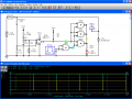
See the attached for a simulation. If Rload is around 100 Ohms, the comparator doesn't trip; if around 80, it does. I just threw it together, and tossed in my 4093 logic.

Rwire and C2 are just there to give a relatively slow rise to the 120v rail; that's why you can see the comparator toggle states. CMD1 sets the inititial voltage of the 120v rail to 0.

I'm using 5v for both the comparator and 4093 supplies. The 4093's have mighty low current output; that's why I tripled 'em up to drive the LED. Still not enough really - better to use the output to switch a transistor or something.
 

Attachments

Last edited:

SgtWookie

Joined Jul 17, 2007
22,230
Ok, I can do that.

As far as the voltage drop. It will be 100-300mV when I compare. You mentioned I might not be able to do that with a comparator?
No, you wouldn't be able to do that with a single supply opamp unless it had rail-to-rail inputs. Neither the LM358 nor the LF353 nor 741 would work.

However, an LM339, LM393 or LM2903 comparator would.

Does that still apply to this? It would seem I could set the reference voltage say at 5v the IC could be driven with 12v. Then I could compare the difference between 5v and 5v + 150mv. So then the comparator would not be too close to its supply voltage and it would compare fine.
No, you're overcomplicating things. Have a look at the simulation I threw together. R6 is now on the return side of Rload.

Just in case R6 gets vaporized, it might be a good idea to have a very small, fast-blow fuse from R6 to the comparator input, with a 1k resistor or 2.5v-4.7v Zener to ground.
 
Last edited:

Thread Starter

HellTriX

Joined Apr 11, 2008
83
What are you trying to do? I assume the mΩ is MegΩ, but small m usually means milli (1/1000).
Thats a milli ohm. Basicly the plate my mosfets are mounted to are slightly undersized and I expect a voltage drop across it as the load increases. Was just going to measure the voltage drop and tell the driver chip to stop going high if the voltage drop got too high (too much current).


Thanks SgtWookie, I will try to find some LM339s now :)
Will do some more simulations and maybe build a test curcuit. Got a test at the university tomorrow so putting some extra time into studying. So this current project might take a few days to get together.
 

SgtWookie

Joined Jul 17, 2007
22,230
Yeppers, RS indeed carries the LM339's.

Hmm, what is the plate attached to? If it's the source, sure you could monitor that. You'd have fun trying to measure Vdrop on the drain side. :eek:

Offhand, I can't think of a good way to do that - as soon as you discharged the gates on your big N-ch MOSFETS, Vds would jump back to 120v, frying the comparator. As it is, the LM339 is limited to -0.3 to 36v on either input.

Perhaps you could use a high-value resistor and clamping diodes or a Zener to keep the input within range. Yeah, that might work. A 12k, 2W resistor from the noninverting input to the drain side of your MOSFETs, with a Zener of say, 4.7v (basically anything from perhaps 3.9v to 15v) to ground. That would give you a maximum of 9.6mA current through the resistor and the Zener, 1.1W dissipation in the resistor, less than 1/20W in the Zener. It won't even break a sweat. :) With virtually no capacitance on the input, it won't take long for the comparator to settle down - but may get "false triggers" if you try to sample it too soon after the MOSFETs have been turned on.

You followin' me, Willis? ;)
 

Thread Starter

HellTriX

Joined Apr 11, 2008
83
Yeah I was thinking of using a zener and a resistor to keep the voltage within range. I just didn't want to say it here and sound like a noob for not knowing of a better way :)
 

SgtWookie

Joined Jul 17, 2007
22,230
OK, do you want to be able to trip the total current through the load & MOSFETS like I showed in the last thing, along with tripping if the Vf across the MOSFETS are too high?
 

Thread Starter

HellTriX

Joined Apr 11, 2008
83
Not sure I understood that.

I do want to turn off the mosfets when the current (voltage drop gets too high). I know it won't be very accurate as the voltage would just kick back up, but I was hoping that it would find an oscillation point at which would keep the total current flow close too the set amount.
 

SgtWookie

Joined Jul 17, 2007
22,230
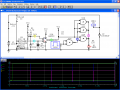
Ok, here's iteration #2.

I got rid of R6.
Rwire and C2 are still necessary just for simulation purposes. Actually, I could set it up differently, but I'm lazy and tired at the moment, so there. :p

Since this sim doesn't have your MOSFETs in the library and I can't add them, I just stacked four IRF640's on top of each other and put a constant 10v on their combined gates. I had to fiddle with R1 and Rload to account for the fact that RdsON with just four IRF640's is going to be higher than your 10 newer MOSFETS.

Anyway, you should be able to barely make out that the noninverting input is passing the inverting input's threshold, which causes the LM339's output to toggle high. You had that 1kHz square wave in your simulation, but I forgot whether it was spending most of it's time high, or low. :confused:

Anyway, if you wanted this thing to control the max current, it's just about there - if your driver takes an inverted logic input. Otherwise, the inputs to the comparator need to be swapped, and the NAND logic modified. There needs to be a fixed time delay in there somewhere, too.

But, I'm tired - time to hit the rack.
 

Attachments

Thread Starter

HellTriX

Joined Apr 11, 2008
83
That looks pretty dang close to the picture I had in my head. I have a hard time getting them to come out. I tend to do much better just designing circuits on the protoboard. Then when I get stuck I just build what I have into a simulator and then I can refine it there. Its hard for me to do the simulation first then the design. I'm an inverted person. :D
But when I see expert work like yours, its no problem to prototype that and play around with it. I usually buffer everything with extra resistors until I know I'm not gonna blow stuff up. (or ask silly questions like the one about the 741 being able to direct connect to the rails).

Its exciting to know that my circuit is getting near to the point where I can etch my own board. I have all the stuff and haven't used it yet.

Its also good that I'm finally starting to add protection circuits to my little projects.

Anyway, time for sleep, then school, then homework, then a date with my teacher, might have time left over to play with my circuits.
 

Thread Starter

HellTriX

Joined Apr 11, 2008
83
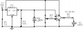
I get my parts tomorrow or Thursday. So I while dinking around to see how sensitive the 741 could be I built this lil circuit.
My 12v battery charger was not charging this leadacid battery so I built a circuit out of a regulator and fed it 16-17 volts, look at that, its now charging at 900mA at 14.86v. Figured I would max it out and let the chip current limit itself lol. But since I had it strung together with some pretty low gauge wire, i measured a 51.8 millivolt drop between to portions of wire going to the positive terminal of the battery. I figured this would be a good test. I hooked up the 741 ran in open loop and adjusted the pot until I got the lead to change states. Well I couldn't get it to do much other then go on and off. When I measured between the output from the regulator and adjusted it to the brink on each side of the on/off state, then moved the wire over to the other side of the voltage drop and couldn't get the state to change. I didn't expect much. I might try it with a higher value pot but don't expect much from that either.
Was just bored and playing. Waiting for my parts to arrive. I gotta reconfigure one of my H-bridges to drive a transformer that I found but I cant remember why I wanted too.
 

Attachments

SgtWookie

Joined Jul 17, 2007
22,230
Well, you're trying to use the 741 as a comparator; you're running it open-loop. This is very hard on it's output circuitry, as it's always in saturation unless the noninverting input = inverting input, less the offset voltage. The open-loop gain for the 741 is somewhere around 200,000.

You sure connected up the LM317 regulator strangely!

With the LM317, start by connecting a 120 Ohm resistor from the output to the Adj terminal (labeled COM in your schematic.) This is to take care of the minimum 10mA current required to obtain guaranteed regulation. Then use a fixed or variable resistor from the Adj terminal to ground.

Note that you also need a 0.1uF cap on the output. This is to prevent oscillations. It's also a good idea to use a 10uF cap or larger to help in transient supression.
 

Thread Starter

HellTriX

Joined Apr 11, 2008
83
ya, I made the circuit then came down stairs and made the circuit wrongly in the capture tool hehe. honest! :)

I do much better when I design with components. I got a box of parts today, get my next box tomorrow with my lm339s and some other stuff. Gonna build the buck converter and try building the comparator circuit.

If I get time between company coming over :confused:

So much stuff so little time.
 
Top